Ford Mustang (1999-2004) Service Manual: Installation
1. Make sure the anti-rattle spring is correctly positioned in the caliper.
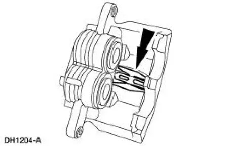
2. CAUTION: Make sure guide pin boots are correctly seated or damage to guide pins can occur.
Install the disc brake caliper.
1. Hold the guide pins stationary.
2. Install the caliper bolts.
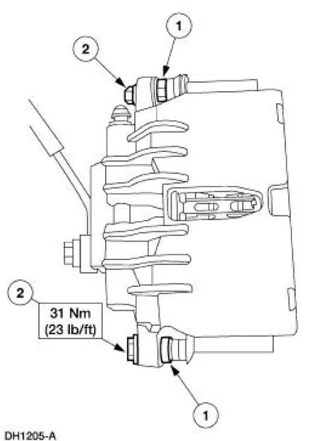
3. NOTE: Use new copper washers.
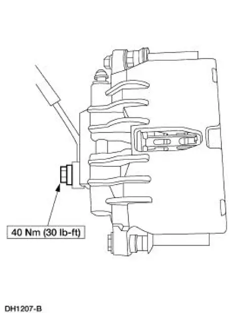
Install the front brake hose.
4. Bleed the caliper.
5. Install the wheel and tire assembly.
6. Fill the brake master cylinder reservoir (2K478) with clean High Performance DOT 3 Brake Fluid C6AZ-19542-AB or equivalent DOT 3 fluid meeting Ford specification ESA-M6C25-A. Install brake master cylinder filler cap (2162).
7. Check the brake system operation.
 Removal
1. Raise and support the vehicle.
2. Remove the wheel and tire assembly.
3. WARNING: Brake fluid contains polyglycol ethers and polyglycols.
Avoid contact
with eyes. Wash hands thoroughly ...
 Brake Caliper - Cobra
Removal
1. Raise and support the vehicle.
2. Remove the tire and wheel assembly.
3. Remove the caliper locating pin E-clip.
4. Remove the caliper locating pin.
5. Remove the front brake ...
Other materials:
Flywheel Ring Gear
Removal
1. Remove the flywheel.
2. WARNING: This procedure should be carried out only by a
correctly equipped and
experienced acetylene torch operator. Tongs must be used or asbestos gloves
worn
when handling the heated flywheel ring gear. Failure to f ...
System Flushing - CIII Power Steering Pump
WARNING: Do not mix oil types. Any mixture or any unapproved oil can
lead to seal
deterioration and leaks. A leak can ultimately cause loss of fluid, which can
result in a loss of
power steering assist.
1. Remove the fuel pump fuse from the battery junction ...
Front Seat Cushion
Disassembly and Assembly
All vehicles
1. Remove the seat track. For additional information, refer to Seat Track
in this section.
2. Remove the seat backrest. For additional information, refer to Front Seat
Backrest in this
section.
Vehicles with powe ...
