
Ford Mustang (1999-2004) Service Manual: Canister Vent Solenoid Closing Procedure
Special Tool(s)
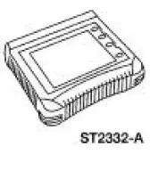 |
Worldwide Diagnostic System (WDS) 418-F224, New Generation STAR (NGS) Tester 418-F052, or equivalent scan tool |
CAUTION: The canister vent solenoid must not be energized for more than nine minutes at one time. Once the canister vent solenoid is energized and de-energized, adequate time must be allowed for the component to cool adequately. Failure to allow the component to cool may create a false failure in the diagnostics, causing unnecessary repairs.
1. Connect the scan tool and select the output test mode.
2. If PID monitors are not active, select PIDs.
3. Select the fuel tank pressure (FTP) and the volts (V) parameter identification (PID) for monitoring.
4. Select the ALL OFF mode.
5. Close the canister vent solenoid by pushing the START button on the scan tool.
 Pinpoint Tests
NOTE: Reinstall or install new evaporative emission hose clamps
removed or damaged during testing
procedures.
PINPOINT TEST A: DTC P0442 SMALL LEAK IN EVAP SYSTEM
Test Step
Result / Action to ...
 Evaporative Emission System Leak Test
Special Tool(s)
Evaporative Emission System
Tester 310-F007
(134-00056) or equivalent
Worldwide Diagnostic System
(WDS)
418-F224,
New Generation STAR (NGS)
Tester
...
Other materials:
Parking, Rear and License Lamps
Refer to Wiring Diagrams Cell 92 , Exterior for schematic and connector
information.
Special Tool(s)
73 III Automotive Meter or
equivalent
105-R0057
Inspection and Verification
1. Verify the customer concern by operating the parking lamps ...
Installation
1. Inspect the pinion flange seal journal for rust, nicks, and scratches
prior to installing the flange.
Polish the seal journal with fine crocus cloth, if necessary.
2. Lubricate the pinion flange splines.
Use SAE 80W-90 Premium Rear Axle Lubricant XY-80 ...
Torque Converter Impeller to Pump Stator Interference
Check
1. NOTE: Front pump support may remain in front pump support and gear
during this test.
Position the front pump support with the splines up.
2. Mount the torque converter on the front pump support with the splines on
the one-way clutch
inner race, engaging t ...
