Ford Mustang (1999-2004) Service Manual: Evaporative Emissions (Diagnosis and Testing)
Special Tool(s)
 |
Evaporative Emission System Leak Tester 310-F007 (134-00056) or equivalent |
 |
Worldwide Diagnostic System (WDS) 418-F224, New Generation STAR (NGS) Tester 418-F052, or equivalent scan tool |
Evaporative Emission System
 Evaporative Emissions (Description and Operation)
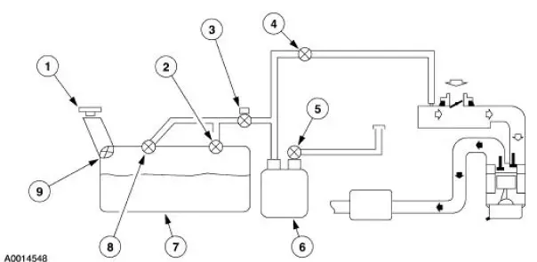
Component Location
The evaporative emission system:
is equipped with an on-board refueling vapor recovery (ORVR) system.
prevents hydrocarbon emissions from reaching the atmosphere.
...
 Principles of Operation
Evaporative Emission (EVAP) Canister Purge Valve
The EVAP canister purge valve is controlled by the powertrain control
module (PCM). The EVAP
canister purge valve controls the flow of fuel vapors ...
Other materials:
Differential Housing Cover
Removal
1. Raise and support the vehicle.
2. NOTE: Empty the lubricant into a clean container for reuse.
Remove the differential housing cover (4033).
1. Remove the 10 bolts and drain the lubricant from the differential
housing (4010).
2. Remove the d ...
Warning lamps and indicators
These indicators can alert you to a vehicle condition that may become
serious enough to cause expensive repairs. Many lights will illuminate
when you start your vehicle to make sure they work. If any light remains
on after starting the vehicle, refer to the re ...
Switch - Seat Regulator Control
Removal and Installation
1. Disconnect the battery. For additional information, refer to Section.
2. Remove the screws and position the seat regulator control switch aside.
3. Disconnect the electrical connector and remove the seat regulator control
swit ...
