Ford Mustang (1999-2004) Service Manual: Evaporative Emissions (Description and Operation)
Component Location
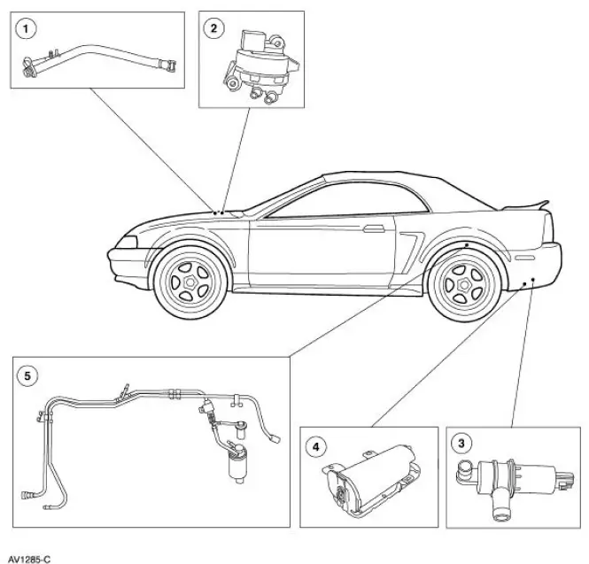
The evaporative emission system:
- is equipped with an on-board refueling vapor recovery (ORVR) system.
- prevents hydrocarbon emissions from reaching the atmosphere.
- stores fuel vapors in the evaporative emission (EVAP) canister that are generated during vehicle operation or hot soak, or vehicle refueling, until they can be consumed by the engine.
- routes the stored fuel vapors to the engine during engine operation.
- is controlled by the powertrain control module (PCM) which uses various sensor inputs to calculate the desired amount of purge flow. The PCM regulates the purge flow, induced by the application of intake manifold vacuum, by varying the duty cycle applied to the EVAP canister purge valve.
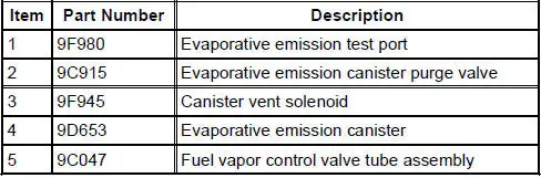
- has an evaporative emission test port for test purposes.
The fuel vapors are routed:
- from the fuel tank through the fuel vapor control valve and fuel vapor vent valve.
- to the EVAP canister through a vapor line.
- to the engine when the EVAP canister purge valve is opened by the PCM.
The fuel tank pressure (FTP) sensor:
- monitors the pressure levels in the fuel tank.
- communicates the pressure reading to the PCM during the OBDII leak test.
- is located in-line above the fuel tank and is serviced as part of the fuel vapor control valve tube assembly.
The evaporative emission canister:
- is located in the left rear quarter panel.
- contains activated carbon.
- stores fuel vapor.
The fuel tank filler cap:
- relieves system pressure above 14 kPa (56.21 inches H 2 O).
- relieves system vacuum below 3.8 kPa (15.26 inches H 2 O).
The canister vent solenoid:
- is normally open.
- seals the EVAP system for the inspection and maintenance (I/M 240) test and OBDII leak and pressure tests.
- is mounted to the evaporative emission canister.
- is repaired as a separate item.
The evaporative emission (EVAP) canister purge valve:
- is normally closed.
- regulates purging of the EVAP canister.
- is controlled by the PCM.
- is located in the right front inner fender well.
The fuel vapor control valve tube assembly:
- consists of the fuel vapor control valve, fuel vapor vent valve and an in-line fuel tank pressure sensor.
- prevents suspended liquid fuel from being drawn into the evaporative emission canister along with the fuel vapors.
- returns the liquid to the fuel tank.
- includes a fresh air transfer tube routing fresh air between the canister vent solenoid hose and the fuel tank filler pipe assembly.
- requires two grommets to seal the fuel vapor control valve and fuel vapor vent valve to the fuel tank.
The evaporative emission (EVAP) system monitor:
- is a self-test strategy within the PCM, which tests the integrity of the EVAP system.
- monitors the EVAP system for leaks.
- monitors electronic EVAP components for irrationally high or low voltages.
- monitors for correct EVAP system operation.
- utilizes intake manifold vacuum to test the EVAP system and involves several stages.
The evaporative emission (EVAP) test port:
- is used to connect the Evaporative Emission System Leak Tester to the EVAP system.
- is located on the EVAP canister purge outlet tube near the EVAP canister purge valve.
 Evaporative Emissions
General Specifications
Torque Specifications
...
 Evaporative Emissions (Diagnosis and Testing)
Special Tool(s)
Evaporative Emission System
Leak Tester
310-F007 (134-00056) or
equivalent
Worldwide Diagnostic System
(WDS)
418-F224,
New Generation STAR (NGS)
Te ...
Other materials:
Vehicle certification label
The National Highway Traffic Safety
Administration Regulations require
that a Safety Compliance Certification
Label be affixed to a vehicle and
prescribe where the Safety Compliance
Certification Label may be located.
The Safety Compliance Certification
Labe ...
Air Cleaner - 4.6L (2V) and 4.6L (4V)
Removal and Installation
Mach I
1. Disconnect the air intake scoop outlet tube.
All vehicles
2. Remove the air cleaner outlet tube from the throttle body. For
additional information, refer to Air
Cleaner Outlet Pipe-4.6L (2V) or Air Cleaner Outlet Pipe- ...
Four Wheel Anti-Lock Brake System (4WABS) Hydraulic Control Unit (HCU)
NOTE: This procedure only needs to be performed if the 4-wheel
anti-lock brake (4WABS) hydraulic
control unit (HCU) has been installed new or if the HCU lines have been
opened.
1. Clean all dirt from and remove the brake master cylinder filler cap
...
