Ford Mustang (1999-2004) Service Manual: Pinpoint Tests
NOTE: Reinstall or install new evaporative emission hose clamps removed or damaged during testing procedures.
PINPOINT TEST A: DTC P0442 SMALL LEAK IN EVAP SYSTEM
| Test Step | Result / Action to Take |
|
NOTE: Condition P0442 DTC set: less than 0.625 kPa (2.5 inches H 2 O) bleed-up over 15 seconds at 75% fuel fill. Vapor generation limit: more than 0.625 kPa (2.5 inches H 2 O) over 120 seconds. |
|
| A1 VISUALLY INSPECT THE COMPONENTS FOR SMALL LEAKS | Yes REPAIR or INSTALL new components as necessary.GO to A2 . No GO to A2 . |
|
|
| A2 CHECK AT THE EVAP TEST PORT FOR SMALL SYSTEM LEAKS | Yes GO to A3 . No GO to A4 . |
|
|
| A3 VISUALLY INSPECT THE FUEL FILLER CAP | Yes INSTALL a new fuel filler cap. GO to A4 . No GO to A4 . |
|
|
| A4 CHECK FOR SMALL LEAKS AT THE FUEL FILLER CAP AND EVAP TEST PORT | Yes REPAIR or INSTALL new components as necessary. GO to A5 . No INSTALL the fuel filler cap. CARRY OUT the evaporative emission system leak test. REFER to Evaporative Emission System Leak Test in this section. If the system passes the leak test, CARRY OUT the evaporative emissions repair verification drive cycle. REFER to Evaporative Emission Repair Verification Drive Cycle in this section. |
|
|
| A5 CHECK FOR CONCERN OTHER THAN THE FUEL FILLER CAP | Yes CARRY OUT the evaporative emission system leak test. REFER to Evaporative Emission System Leak Test in this section. If the system passes the leak test, CARRY OUT the evaporative emission repair verification drive cycle. REFER to Evaporative Emission Repair Verification Drive Cycle in this section. No INSTALL the fuel filler cap. GO to A6 . |
|
|
| A6 CHECK FOR SMALL LEAK WITH TESTER SET AT FILL POSITION | Yes GO to A7 . No DISCONTINUE pressurizing the system. GO to A8 . |
|
|
| A7 CHECK FOR LEAKS IN THE COMPLETE EVAP SYSTEM | Yes REPAIR or INSTALL new components as necessary. CARRY OUT the evaporative emission system leak test. REFER to Evaporative Emission System Leak Test in this section. If the system passes the leak test, CARRY OUT the evaporative emissions repair verification drive cycle. REFER to Evaporative Emission Repair Verification Drive Cycle in this section. No DISCONTINUE pressurizing the system. GO to A8 . |
|
|
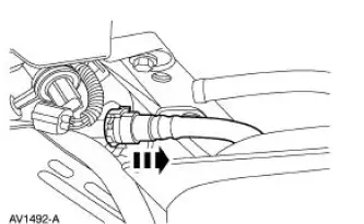
| A8 CHECK FOR SMALL LEAK FROM THE EVAP RETURN TUBE TO THE FUEL VAPOR TEE | Yes REPAIR or INSTALL new components as necessary. REPEAT Step A6 to verify the repair. GO to A9 . No GO to A9 . |
|
|
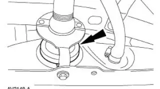
| A9 CHECK FOR SMALL LEAK BETWEEN EVAP CANISTER AND FUEL TANK FILLER PIPE | Yes REPAIR or INSTALL new components as necessary. GO to A10 . No GO to A10 . |
|
|
| A10 CHECK EVAP SYSTEM AT FUEL FILLER PIPE | Yes RESTORE the system to normal operation. CARRY OUT the evaporative emission system leak test. REFER to Evaporative Emission System Leak Test in this section. If the system passes the leak test, CARRY OUT the evaporative emissions repair verification drive cycle. REFER to Evaporative Emission Repair Verification Drive Cycle in this section. No GO to A6 . |
|
|
PINPOINT TEST B: DTC P0455 MAJOR LEAK OR NO FLOW DETECTED OR DTC P1443 VERY SMALL OR NO PURGE FLOW DETECTED IN SYSTEM
| Test Step | Result / Action to Take |
| NOTE: Condition DTC P0455 set: -1.74 kPa (-7.0 inches H 2 O) over 30 seconds. | |
| NOTE: Condition DTC P1443 set: -1.74 kPa (-7.0 inches H 2 O) over 30 seconds with more than 0.02 lb/min vapor flow. | |
| B1 CHECK FOR DIAGNOSTIC TROUBLE CODE P0455 OR P1443 | Yes GO to B2 . No GO to B3 . |
|
|
| B2 VISUALLY CHECK FOR GROSS EVAP SYSTEM LEAKS | Yes REPAIR or INSTALL new EVAP components as necessary. GO to B3 . No GO to B3 . |
|
|
| B3 CHECK FOR EVAP SYSTEM LEAKS | Yes GO to B4 . No VERIFY that the fuel filler cap is installed correctly. REPAIR or INSTALL new components as necessary. CARRY OUT the evaporative emission system leak test. REFER to Evaporative Emission System Leak Test in this section. If the system passes the leak test, CARRY OUT the evaporative emission repair verification drive cycle. REFER to Evaporative Emission Repair Verification Drive Cycle in this section. |
|
|
| B4 CHECK FOR BLOCKAGE BETWEEN THE EVAP CANISTER PURGE VALVE AND FUEL VAPOR TEE | Yes GO to B5 . No INSTALL a new vapor line between the EVAP canister purge valve and the fuel vapor tee. CARRY OUT the evaporative emission system leak test. REFER to Evaporative Emission System Leak Test in this section. If the system passes the leak test, CARRY OUT the evaporative emission repair verification drive cycle. REFER to Evaporative Emission Repair Verification Drive Cycle in this section. |
|
|
| B5 CHECK FOR BLOCKAGE BETWEEN FUEL FILLER PIPE AND THE FUEL VAPOR TEE | Yes GO to B6 . No INSTALL new fuel tank vapor line(s). REPEAT pinpoint test Step B5 to verify the repair. CARRY OUT the evaporative emission system leak test. REFER to Evaporative Emission System Leak Test in this section. If the system passes the leak test, CARRY OUT the evaporative emission repair verification drive cycle. REFER to Evaporative Emission Repair Verification Drive Cycle in this section. |
|
|
| B6 CHECK FOR FAILED EVAP CANISTER PURGE VALVE OR FUEL TANK PRESSURE SENSOR | Yes INSTALL a new EVAP canister purge valve. REFER to Evaporative Emission Canister Purge Valve in this section. CARRY OUT the evaporative emission system leak test. REFER to Evaporative Emission System Leak Test in this section. If no leak is detected, CARRY OUT the evaporative emissions repair verification drive cycle. REFER to Evaporative Emission Repair Verification Drive Cycle in this section. No INSTALL a new fuel tank pressure sensor. REFER to Fuel Tank Pressure Sensor in this section. CARRY OUT the evaporative emission system leak test. REFER to Evaporative Emission System Leak Test in this section. If the system passes the leak test, CARRY out the evaporative emission repair verification drive cycle. REFER to Evaporative Emission Repair Verification Drive Cycle in this section. |
|
|
PINPOINT TEST C: DTC P1450 EXCESSIVE VACUUM DETECTED IN THE FUEL TANK
| Test Step | Result / Action to Take |
|
NOTE: Condition P1450 DTC set: more than -1.79 kPa (-7.2 inches H 2 O) over 30 seconds. |
|
| C1 CHECK FOR VISUAL CAUSES OF EXCESSIVE FUEL TANK VACUUM | Yes REMOVE any contamination or foreign material around fuel vapor hoses and tubes. REPAIR the hoses, tubes or components as necessary. After all visual concerns are repaired, GO to C2 . No GO to C2 . |
|
|
| C2 CHECK FOR BLOCKAGE BETWEEN EVAP TEST PORT AND CANISTER VENT SOLENOID | Yes GO to C3 . No GO to Pinpoint Test D . |
|
|
| C3 CHECK FOR BLOCKAGE BETWEEN THE FUEL FILLER PIPE AND THE FUEL VAPOR TEE | Yes GO to C4 . No GO to Pinpoint Test D . |
|
|
| C4 CHECK FOR FUEL TANK PRESSURE SENSOR PID WITHOUT PRESSURE APPLIE | Yes GO to C5 . No REFER to Powertrain Control/Emissions Diagnosis (PC/ED) manual to continue diagnosis. |
|
|
| C5 CHECK FOR STUCK OPEN EVAP CANISTER PURGE VALVE CONDITION AT IDLE | Yes INSTALL a new EVAP canister purge valve. REFER to Evaporative Emission Canister Purge Valve in this section. CARRY OUT an EVAP system leak test. REFER to Evaporative Emission System Leak Test in this section. If the system passes the leak test, CARRY OUT an evaporative emissions repair verification drive cycle. REFER to Evaporative Emission Repair Verification Drive Cycle in this section. No CARRY OUT the EVAP system leak test. REFER to Evaporative Emission System Leak Test in this section. If the system passes the leak test, CARRY OUT the evaporative emissions repair verification drive cycle. REFER to Evaporative Emission Repair Verification Drive Cycle in this section. |
|
|
PINPOINT TEST D: HISSING SOUND WHEN REMOVING FUEL CAP
| Test Step | Result / Action to Take |
| D1 TEST FOR FUEL TANK PRESSURE SENSOR OPERATION | Yes GO to D2 . No GO to D3 |
|
|
| D2 TEST FOR BLOCKAGE IN VENTING PORTION OF EVAP SYSTEM | Yes CARRY OUT the evaporative emission repair verification drive cycle. REFER to Evaporative Emission Repair Verification Drive Cycle in this section. No GO to D7 . |
|
|
| D3 TEST FOR FUEL TANK PRESSURE SENSOR OPERATION | Yes GO to D4 . No REFER to the Powertrain Control/Emissions Diagnosis (PC/ED) manual. |
|
|
| D4 TEST TO DETERMINE BLOCKAGE LOCATION | Yes GO to D5 . No GO to D7 . |
|
|
| D5 TEST FOR PINCHED FUEL VAPOR CONTROL VALVE TUBE | Yes INSTALL a new fuel vapor control valve tube assembly. REFER to Fuel Vapor Control Tube Assembly Valve in this section. CARRY OUT a leak test. REFER to Evaporative Emission System Leak Test in this section. If the system passes the leak test, CARRY OUT the evaporative emission repair verification drive cycle. REFER to Evaporative Emission Repair Verification Drive Cycle in this section. No GO to D6 . |
|
|
| D6 TEST FOR BLOCKAGE IN FUEL FILLER TUBE ASSEMBLY | Yes INSTALL a new fuel vapor control valve tube assembly. REFER to Fuel Vapor Control Tube Assembly Valve in this section. CARRY OUT a leak test. REFER to Evaporative Emission System Leak Test in this section. If the system passes the leak test, CARRY OUT the evaporative emission repair verification drive cycle. REFER to Evaporative Emission Repair Verification Drive Cycle in this section. No INSTALL a new fuel filler pipe assembly. REFER to Section. CARRY OUT a leak test. REFER to Evaporative Emission System Leak Test in this section. If the system passes the leak test, CARRY OUT the evaporative emission repair verification drive cycle. REFER to Evaporative Emission Repair Verification Drive Cycle in this section. |
|
|
| D7 TEST FOR BLOCKAGE IN FRESH AIR VENT HOSE | Yes INSTALL a new fresh air vent hose. CARRY OUT a leak test. REFER to Evaporative Emission System Leak Test in this section. If the system passes the leak test, CARRY OUT the evaporative emission repair verification drive cycle. REFER to Evaporative Emission Repair Verification Drive Cycle in this section. No GO to D8 . |
|
|
| D8 TEST FOR BLOCKAGE IN THE FRESH AIR TUBE ON THE FUEL FILLER PIPE ASSEMBLY | Yes INSTALL a new fuel filler pipe assembly. REFER to Section. CARRY OUT a leak test. REFER to Evaporative Emission System Leak Test in this section. If the system passes the leak test, CARRY OUT the evaporative emission repair verification drive cycle. REFER to Evaporative Emission Repair Verification Drive Cycle in this section. No GO to D9 . |
|
|
| D9 TEST FOR BLOCKAGE IN THE TANK VAPOR VALVE ASSEMBLY-FRESH AIR TUBE | Yes INSTALL a new tank vapor valve assembly-fresh air tube. CARRY OUT a leak test. REFER to Evaporative Emission System Leak Test in this section. If the system passes the leak test, CARRY OUT the evaporative emission repair verification drive cycle. REFER to Evaporative Emission Repair Verification Drive Cycle in this section. No GO to D10 . |
|
|
| D10 TEST FOR BLOCKAGE IN CANISTER VENT SOLENOID HOSE | Yes INSTALL a new canister vent solenoid hose. CARRY OUT a leak test. REFER to Evaporative Emission System Leak Test in this section. If the system passes the leak test, CARRY OUT the evaporative emission repair verification drive cycle. REFER to Evaporative Emission Repair Verification Drive Cycle in this section. No GO to D11 . |
|
|
| D11 TEST FOR BLOCKAGE IN CANISTER VENT SOLENOID | Yes INSTALL a new canister vent solenoid. REFER to Evaporative Emission Canister Vent Solenoid in this section. CARRY OUT a leak test. REFER Evaporative Emission System Leak Test in this section. If the system passes the leak test, CARRY OUT the evaporative emission repair verification drive cycle. REFER to Evaporative Emission Repair Verification Drive Cycle in this section. No GO to D12 . |
|
|
| D12 TEST FOR BLOCKAGE IN EVAPORATIVE EMISSIONS CANISTER | Yes INSTALL a new evaporative emissions canister. REFER to Evaporative Emission Canister in this section. CARRY OUT a leak test. REFER to Evaporative Emission System Leak Test in this section. If the system passes the leak test, CARRY OUT the evaporative emission repair verification drive cycle. REFER to Evaporative Emission Repair Verification Drive Cycle in this section. No GO to D13 . |
|
|
| D13 TEST FOR BLOCKAGE IN CANISTER INLET ELBOW | Yes INSTALL a new evaporative emissions canister inlet elbow. CARRY OUT a leak test. REFER to Evaporative Emission System Leak Test in this section. If the system passes the leak test, CARRY OUT the evaporative emission repair verification drive cycle. REFER to Evaporative Emission Repair Verification Drive Cycle in this section. No INSTALL a new fuel vapor control valve tube assembly. REFER to Fuel Vapor Control Tube Assembly Valve in this section. CARRY OUT a leak test. REFER to Evaporative Emission System Leak Test in this section. If the system passes the leak test, CARRY OUT the evaporative emission repair verification drive cycle. REFER to Evaporative Emission Repair Verification Drive Cycle in this section. |
|
PINPOINT TEST E: EXCESSIVE FUEL ODOR
| Test Step | Result / Action to Take |
| E1 EVAPORATIVE EMISSION SYSTEM LEAK TEST | Yes GO to E2 . No GO to E3 . |
|
|
| E2 CARRY OUT THE EVAPORATIVE EMISSION SYSTEM RUNNING LOSS MONITOR REPAIR VERIFICATION DRIVE CYCLE | Yes For DTCs P0442, P0455, P1443, and P1450 REFER to the Diagnostic Trouble Code (DTC) Index in this section. For all other DTCs, REFER to the Powertrain Control/Emissions Diagnosis (PC/ED) manual for diagnosis of the DTCs. No EVAP system diagnosis complete. REFER to Symptom Chart. |
|
|
| E3 ISOLATE SYSTEM LEAK FROM FRONT TO REAR | Yes GO to E4 . No GO to E9 . |
|
|
| E4 TEST FUEL VAPOR HOSE FROM FUEL TANK TO TUBE ASSEMBLY FUEL SUPPLY-RETURN AND VAPOR | Yes GO to E5 . No INSTALL a new fuel vapor return hose. CARRY OUT a leak test. REFER to Evaporative Emission System Leak Test on this section. If the system passes the leak test, CARRY OUT the evaporative emission repair verification drive cycle. REFER to Evaporative Emission Repair Verification Drive Cycle in this section. |
|
|
| E5 TEST THE FUEL SUPPLY-RETURN AND VAPOR TUBE ASSEMBLY | Yes GO to E6 . No INSTALL a new fuel supply-return and vapor tube assembly. CARRY OUT a leak test. REFER to Evaporative Emission System Leak Test on this section. If the system passes the leak test, CARRY OUT the evaporative emission repair verification drive cycle. REFER to Evaporative Emission Repair Verification Drive Cycle in this section. |
|
|
| E6 TEST FOR EVAPORATIVE EMISSIONS TEST PORT LEAK | Yes INSTALL a new evaporative emissions test port. REFER to Evaporative Emission Test Port . CARRY OUT a leak test. REFER to Evaporative Emission System Leak Test on this section. If the system passes the leak test, CARRY OUT the evaporative emission repair verification drive cycle. REFER to Evaporative Emission Repair Verification Drive Cycle in this section. No RECONNECT the evaporative emissions test port tube to the EVAP canister purge outlet tube. GO to E7 . |
|
|
| E7 TEST FOR EVAP CANISTER PURGE OUTLET TUBE LEAK | Yes INSTALL a new EVAP canister purge outlet tube. CARRY OUT a leak test. REFER to Evaporative Emission System Leak Test on this section. If the system passes the leak test, CARRY OUT the evaporative emission repair verification drive cycle. REFER to Evaporative Emission Repair Verification Drive Cycle in this section. No RECONNECT the EVAP canister purge outlet tube. GO to E8 . |
|
|
| E8 TEST FOR LEAK AT EVAPORATIVE EMISSIONS PURGE VALVE | Yes INSTALL a new evaporative emissions canister purge valve. REFER to Evaporative Emission Canister Purge Valve in this section. CARRY OUT a leak test. REFER to Evaporative Emission System Leak Test on this section. If the system passes the leak test, CARRY OUT the evaporative emission repair verification drive cycle. REFER to Evaporative Emission Repair Verification Drive Cycle in this section. No INSTALL a new evaporative emissions return tube. CARRY OUT a leak test. REFER to Evaporative Emission System Leak Test on this section. If the system passes the leak test, CARRY OUT the evaporative emission repair verification drive cycle. REFER to Evaporative Emission Repair Verification Drive Cycle in this section. |
|
|
| E9 TEST FOR BLOCKAGE IN VENTING PORTION OF EVAP SYSTEM | Yes GO to E14 . No GO to E10 . |
|
|
| E10 TEST FOR BLOCKAGE IN THE FRESH AIR VENT HOSE | Yes INSTALL a new fresh air vent hose. CARRY OUT a leak test. REFER to Evaporative Emission System Leak Test in this section. If the system passes the leak test, CARRY OUT the evaporative emission repair verification drive cycle. REFER to Evaporative Emission Repair Verification Drive Cycle in this section. No GO to E11 . |
|
|
| E11 TEST FOR BLOCKAGE IN THE FRESH AIR TUBE ON THE FUEL FILLER PIPE ASSEMBLY | Yes INSTALL a new fuel filler pipe assembly. REFER to Section. CARRY OUT a leak test. REFER to Evaporative Emission System Leak Test in this section. If the system passes the leak test, CARRY OUT the evaporative emission repair verification drive cycle. REFER to Evaporative Emission Repair Verification Drive Cycle in this section. No GO to E12 . |
|
|
| E12 TEST FOR BLOCKAGE IN THE FUEL VAPOR CONTROL VALVE TUBE ASSEMBLY-FRESH AIR TUBE | Yes INSTALL a new fuel vapor control valve tube assembly-fresh air tube. CARRY OUT a leak test. REFER to Evaporative Emission System Leak Test in this section. If the system passes the leak test, CARRY OUT the evaporative emission repair verification drive cycle. REFER to Evaporative Emission Repair Verification Drive Cycle in this section. No GO to E13 . |
|
|
| E13 TEST FOR BLOCKAGE IN CANISTER VENT SOLENOID HOSE | Yes INSTALL a new canister vent solenoid hose. CARRY OUT a leak test. REFER to Evaporative Emission System Leak Test in this section. If the system passes the leak test, CARRY OUT the evaporative emission repair verification drive cycle. REFER to Evaporative Emission Repair Verification Drive Cycle in this section. No INSTALL a new canister vent solenoid. REFER to Evaporative Emission Canister Vent Solenoid in this section. CARRY OUT a leak test. REFER to Evaporative Emission System Leak Test in this section. If the system passes the leak test, CARRY OUT the evaporative emission repair verification drive cycle. REFER to Evaporative Emission Repair Verification Drive Cycle in this section. |
|
|
| E14 TEST FOR LEAK IN EVAPORATIVE EMISSIONS CANISTER | Yes EVAP system diagnosis complete. GO to E18 . No GO to E15 |
|
|
| E15 TEST FOR CANISTER VENT SOLENOID LEAK | Yes INSTALL a new canister vent solenoid. REFER to Evaporative Emission Canister Vent Solenoid in this section. CARRY OUT a leak test. REFER to Evaporative Emission System Leak Test in this section. If the system passes the leak test, CARRY OUT the evaporative emission repair verification drive cycle. REFER to Evaporative Emission Repair Verification Drive Cycle in this section. No GO to E16 . |
|
|
| E16 TEST FOR CANISTER LEAK | Yes INSTALL a new EVAP canister assembly. REFER to Evaporative Emission Canister in this section. CARRY OUT a leak test. REFER to Evaporative Emission System Leak Test in this section. If the system passes the leak test, CARRY OUT the evaporative emission repair verification drive cycle. REFER to Evaporative Emission Repair Verification Drive Cycle in this section. No GO to E17 . |
|
|
| E17 TEST FOR CANISTER INLET ELBOW LEAK | Yes INSTALL a new evaporative emissions canister inlet elbow. CARRY OUT a leak test. REFER to Evaporative Emission System Leak Test in this section. If the system passes the leak test, CARRY OUT the evaporative emission repair verification drive cycle. REFER to Evaporative Emission Repair Verification Drive Cycle in this section. No INSTALL a new fuel vapor control valve tube assembly. REFER to Fuel Vapor Control Tube Assembly Valve in this section. CARRY OUT a leak test. REFER to Evaporative Emission System Leak Test in this section. If the system passes the leak test, CARRY OUT the evaporative emission repair verification drive cycle. REFER to Evaporative Emission Repair Verification Drive Cycle in this section. |
|
|
| E18 TEST FOR LEAKAGE IN FUEL FILLER PIPE GROMMET | Yes INSPECT fuel filler pipe to tank grommet for cuts, abrasions or leaks. REFER to Section for repair procedures. No CARRY OUT a leak test. REFER to Evaporative Emission System Leak Test in this section. If the system passes the leak test, CARRY OUT the evaporative emission repair verification drive cycle. REFER to Evaporative Emission Repair Verification Drive Cycle in this section. |
|
PINPOINT TEST F: UNABLE TO REFUEL VEHICLE (ORVR)
| Test Step | Result / Action to Take |
| F1 TEST THE FUEL FILLER PIPE AND THE FUEL FILLER PIPE CHECK VALVE | Yes GO to F2 . No GO to F10 . |
|
|
| F2 TEST THE EVAP SYSTEM FOR RESTRICTION | Yes GO to F3 . No CARRY OUT the evaporative emissions system leak test. REFER to Evaporative Emission System Leak Test in this section. If the system passes the leak test, CARRY OUT the evaporative emissions repair verification drive cycle. REFER to Evaporative Emission Repair Verification Drive Cycle in this section. |
|
|
| F3 TEST FOR BLOCKAGE IN FRESH AIR VENT HOSE | Yes INSTALL a new fresh air vent hose. CARRY OUT a leak test. REFER to Evaporative Emission System Leak Test in this section. If the system passes the leak test, CARRY OUT the evaporative emission repair verification drive cycle. REFER to Evaporative Emission Repair Verification Drive Cycle in this section. No GO to F4 . |
|
|
| F4 TEST FOR BLOCKAGE IN THE FRESH AIR TUBE ON THE FUEL FILLER PIPE ASSEMBLY | Yes INSTALL a new fuel filler pipe assembly. REFER to Section. CARRY OUT a leak test. REFER to Evaporative Emission System Leak Test in this section. If the system passes the leak test, CARRY OUT the evaporative emission repair verification drive cycle. REFER to Evaporative Emission Repair Verification Drive Cycle in this section. No GO to F5 . |
|
|
| F5 TEST FOR BLOCKAGE IN THE TANK VAPOR VALVE ASSEMBLY-FRESH AIR TUBE | Yes INSTALL a new tank vapor valve assembly-fresh air tube. CARRY OUT a leak test. REFER to Evaporative Emission System Leak Test in this section. If the system passes the leak test, CARRY OUT the evaporative emission repair verification drive cycle. REFER to Evaporative Emission Repair Verification Drive Cycle in this section. No GO to F6 . |
|
|
| F6 TEST FOR BLOCKAGE IN CANISTER VENT SOLENOID HOSE | Yes INSTALL a new canister vent solenoid hose. CARRY OUT a leak test. REFER to Evaporative Emission System Leak Test in this section. If the system passes the leak test, CARRY OUT the evaporative emission repair verification drive cycle. REFER to Evaporative Emission Repair Verification Drive Cycle in this section. No GO to F7 . |
|
|
| F7 TEST FOR BLOCKAGE IN CANISTER VENT SOLENOID | Yes INSTALL a new canister vent solenoid. REFER to Evaporative Emission Canister Vent Solenoid in this section. CARRY OUT a leak test. REFER to Evaporative Emission System Leak Test in this section. If the system passes the leak test, CARRY OUT the evaporative emission repair verification drive cycle. REFER to Evaporative Emission Repair Verification Drive Cycle in this section. No GO to F8 . |
|
|
| F8 TEST FOR BLOCKAGE IN EVAPORATIVE EMISSIONS CANISTER | Yes INSTALL a new evaporative emissions canister. REFER to Evaporative Emission Canister in this section. CARRY OUT a leak test. REFER to Evaporative Emission System Leak Test in this section. If the system passes the leak test, CARRY OUT the evaporative emission repair verification drive cycle. REFER to Evaporative Emission Repair Verification Drive Cycle in this section. No GO to F9 . |
|
|
| F9 TEST FOR BLOCKAGE IN CANISTER INLET ELBOW | Yes INSTALL a new evaporative emissions canister inlet elbow. CARRY OUT a leak test. REFER to Evaporative Emission System Leak Test in this section. If the system passes the leak test, CARRY OUT the evaporative emission repair verification drive cycle. REFER to Evaporative Emission Repair Verification Drive Cycle in this section. No GO to F10 . |
|
|
| F10 TEST FOR PINCHED FUEL VAPOR CONTROL VALVE TUBE | Yes INSTALL a new fuel vapor control valve tube assembly. REFER to Fuel Vapor Control Tube Assembly Valve in this section. CARRY OUT a leak test. REFER to Evaporative Emission System Leak Test in this section. If the system passes the leak test, CARRY OUT the evaporative emission repair verification drive cycle. REFER to Evaporative Emission Repair Verification Drive Cycle in this section. No GO to F11 . |
|
|
| F11 TEST FOR BLOCKAGE IN FUEL FILLER TUBE ASSEMBLY | Yes INSTALL a new fuel vapor control valve tube assembly. REFER to Fuel Vapor Control Tube Assembly Valve in this section. CARRY OUT a leak test. REFER to Evaporative Emission System Leak Test in this section. If the system passes the leak test, CARRY OUT the evaporative emission repair verification drive cycle. REFER to Evaporative Emission Repair Verification Drive Cycle in this section. No INSTALL a new fuel filler pipe assembly. REFER to Section. CARRY OUT a leak test. REFER to Evaporative Emission System Leak Test in this section. If the system passes the leak test, CARRY OUT the evaporative emission repair verification drive cycle. REFER to Evaporative Emission Repair Verification Drive Cycle in this section. |
|
 Inspection and Verification
1. Verify the customer concern is with the evaporative emission (EVAP)
system.
2. Visually inspect for the following obvious signs of mechanical damage.
Visual Inspection Chart
Mechanical
...
 Canister Vent Solenoid Closing Procedure
Special Tool(s)
Worldwide Diagnostic System
(WDS)
418-F224,
New Generation STAR (NGS)
Tester
418-F052, or equivalent scan
tool
CAUTION: The canister vent solenoid must not be ...
Other materials:
Removal
All vehicles
WARNING: To prevent glass splinters from entering eyes or
cutting hands, wear safety
glasses and heavy gloves when cutting glass from the vehicle.
1. Remove the RH and LH windshield side garnish mouldings.
If equipped with a convert ...
Installation
1. Inspect the rear axle pinion flange seal journal for rust, nicks, and
scratches prior to installing
the flange. Polish the seal journal with fine crocus cloth, if necessary.
2. Lubricate the rear axle pinion flange splines.
Use SAE 75W-140 High Performa ...
Inspection and Verification
WARNING: When servicing starter motor or carrying out other underhood
work in the
vicinity of the starter motor, be aware that the heavy gauge battery input lead
at the starter
solenoid is "electrically hot" at all times. A protective cap or boot is
provide ...

