Ford Mustang (1999-2004) Service Manual: External Controls (Diagnosis and Testing)
Refer to Wiring Diagrams Cell 37 , Shift Lock for schematic and connector information.
Refer to Wiring Diagrams Cell 29 , Transmission Control for schematic and connector information.
Special Tool(s)
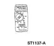 |
73 Digital Multimeter 105-R0051 or equivalent |
Inspection and Verification
1. Verify the customer concern by operating the transmission external control.
2. Visually inspect for obvious signs of mechanical and electrical damage; refer to the following chart:
Visual Inspection Chart
| Mechanical | Electrical |
|
|
3. If the concern is not visually evident, determine the symptom. GO to Symptom Chart .
Symptom Chart
| Condition | Possible Sources | Action |
|
|
|
|
|
|
|
|
|
|
|
|
|
|
|
|
|
|
|
|
|
Pinpoint Tests
PINPOINT TEST A: THE SHIFT INTERLOCK SYSTEM DOES NOT RELEASE/LOCK CORRECTLY
| Test Step | Result / Action to Take |
| A1 TEST THE BRAKE LIGHTS | Yes GO to A2 . No REFER to Section |
|
|
| A2 CHECK CIRCUIT 511 (LG) FOR AN OPEN | Yes GO to A3 . No REPAIR the circuit. TEST the system for normal operation. |
|
|
| A3 CHECK CIRCUIT 294 (WH/LB) FOR AN OPEN | Yes GO to A4 . No REPAIR the circuit. TEST the system for normal operation. |
|
|
| A4 TEST CIRCUIT 1205 (BK) FOR AN OPEN | Yes INSTALL a new shift lock actuator. REFER to Brake Shift Interlock Actuator . TEST the system for normal operation. No REPAIR the circuit. TEST the system for normal operation |
|
PINPOINT TEST B: THE SHIFT CONTROL IS OUT OF CORRECT GEAR RELATIONSHIP
| Test Step | Result / Action to Take |
| B1 CHECK THE SHIFT CONTROL LINKAGE | Yes GO to B2 . No REPAIR as necessary. TEST the system for normal operation. |
|
|
| B2 CHECK THE TRANSMISSION SHIFT CABLE | Yes GO to B3 . No REPAIR as necessary. TEST the system for normal operation. |
|
|
| B3 CHECK THE LINKAGE/CABLE FOR CORRECT GEAR RELATIONSHIP | Yes VERIFY the correct adjustment of the digital transmission range (DTR) sensor. REFER to Section. digital DTR sensor if necessary. TEST the system for normal operation. No ADJUST the transmission shift cable. REFER to Cable Adjustment . TEST the system for normal operation. |
|
PINPOINT TEST C: THE TRANSMISSION CONTROL SWITCH (TCS) IS INOPERATIVE
| Test Step | Result / Action to Take |
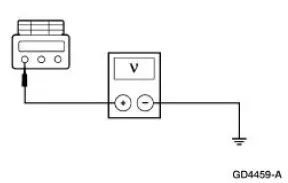
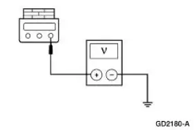
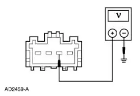
| C1 CHECK THE VOLTAGE TO THE TRANSMISSION CONTROL SWITCH | Yes GO to C2 . No REPAIR the circuit. TEST the system for normal operation. |
|
|
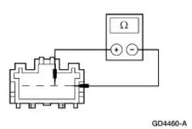
| C2 CHECK THE TCS | Yes GO to C3 . No INSTALL a new TCS. Test the system for normal operation. |
|
|
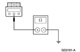
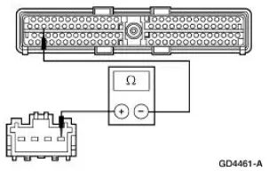
| C3 CHECK CIRCUIT 224 (TN/WH) FOR AN OPEN | Yes REFER to Powertrain Control/Emissions Diagnosis (PC/ED) manual. No REPAIR the circuit. TEST the system for normal operation |
|
 External Controls (Description and Operation)
The transmission shift cable transfers the transmission operating mode from
the gearshift lever to the
automatic transmission (7003). The indicated position of the transmission floor
mounted selecto ...
 Cable Adjustment
1. NOTE: Make sure that the range selector lever is tight
against the rearward overdrive stop.
Place the transmission range selector lever in the overdrive
position.
2. Raise and support the ...
Other materials:
Lamp Assembly - Fog Lamp (GT)
Removal
1. Raise and support the vehicle.
2. Remove the screw.
3. Partially lower the vehicle and remove the fog lamp assembly.
1. Disconnect the electrical connector.
2. Remove the two screws.
3. Remove the fog lamp assembly and replace the bul ...
Main Control Valve Body
Special Tool(s)
Gauge, Transmission Solenoid
Connectors
307-426
Removal
1. Drain transmission fluid and remove the transmission fluid pan and
filter. For additional
information, refer to Fluid Pan, Gasket and Filter .
2. CAUTION: Do not ...
Belt Minder Deactivating/Activating
Preparation
1. Before deactivating/activating the belt minder, set the parking
brake.
2. Place the gearshift in P (Park) (automatic transmission) or the
neutral position (manual
transmission).
3. Place the ignition switch in the OFF position.
...
