Ford Mustang (1999-2004) Service Manual: Front End Body Panels
Torque Specifications
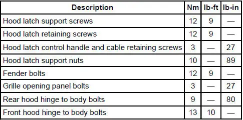
Front End Body Panels
The front end body panel components consist of the following:
- air deflectors
- cowl grille
- fenders
- fender splash shields
- hood
- hood hinges
- hood weatherstrip
- radiator grille opening panel
Fender
Removal and Installation
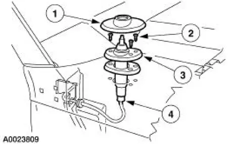
1. On the RH fender, remove the antenna base.
1. Remove the antenna base cap.
2. Remove the screws.
3. Remove the antenna base.
4. Disconnect the antenna cable from the antenna base.
2. Remove the front bumper cover. For additional information, refer to Section.
3. Remove the screw, the two pin-type retainers and the front rocker panel moulding.
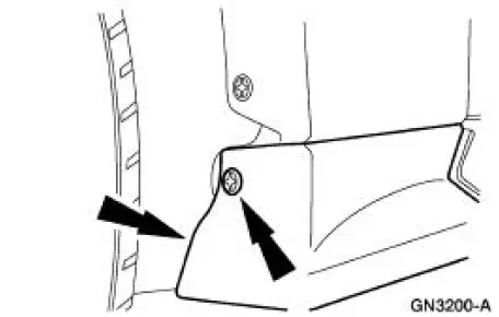
4. Remove the fender splash shield screw.
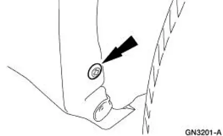
5. NOTE: Position the fender splash shield aside.
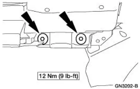
Remove the lower fender bolts and, if equipped, remove the shims.
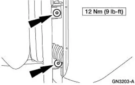
6. Through the door opening, remove the inner fender bolts.
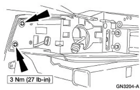
7. Remove the radiator grille opening panel to fender bolts.
8. Remove the upper bolts and the fender.
9. NOTE: On the RH fender, feed the antenna cable through the fender opening.
To install, reverse the removal procedure.
- Check the fender alignment and adjust as needed.
Radiator Grille Opening Panel
Removal and Installation
1. Remove the front bumper cover. For additional information, refer to Section.
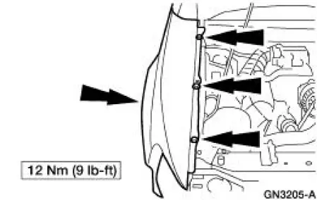
2. Remove the eight bolts (four on each side) and the radiator grille opening panel.
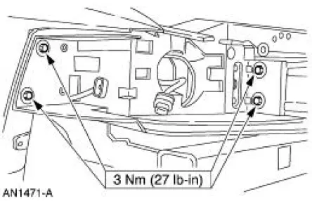
3. To install, reverse the removal procedure.
 Body System (Diagnosis and Testing)
Inspection and Verification
Leaks
NOTE: Trim will reveal the location of most leaks.
1. Remove any trim or carpet in the general area of the leak.
2. Road test or water test the vehicle.
3 ...
 Body Closures
General Specifications
Torque Specifications
Body Closures
The body closures consist of the following components:
door checks
front door
front door latch strikers
front door hinges ...
Other materials:
Handles, Locks, Latches And Mechanisms (Description and Operation)
Lock Cylinders
Individual lock cylinders are repaired by discarding the inoperative
lock cylinder and building a new
lock cylinder using the appropriate lock repair package. The lock repair
package includes a detailed
instruction sheet to build the ...
Sun visors
Slide-On-Rod
Rotate the visor toward the side
window and extend it rearward for
extra sunlight coverage.
Retract the visor before moving it
back toward the windshield and
storing it.
Illuminated Visor Vanity Mirror
Lift the cover to switch on the lamp.
Flex ...
Piston
Special Tool(s)
Piston Pin Tool or equivalent
303-D034 (D81L-6135-A)
Material
Item
Specification
SAE 5W-20 Premium Synthetic
Blend Motor Oil
XO-5W20-QSP or equivalent
WSS-M2C153-
H
Disassembly
1. Using the special tool, ...
