Ford Mustang (1999-2004) Service Manual: Front Seat Backrest
Disassembly and Assembly
All vehicles
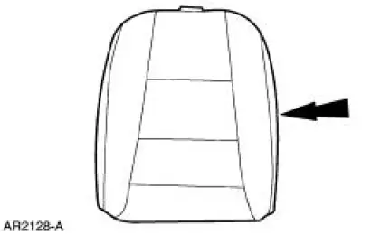
1. Remove the front seat backrest. For additional information, refer to Front Seat Backrest in this section.
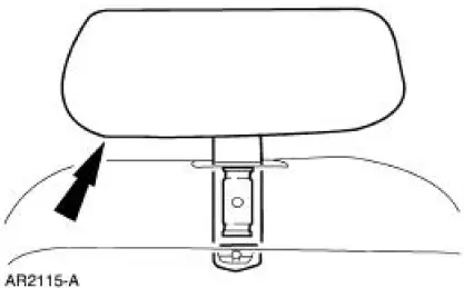
2. Remove the front seat backrest head restraint (611A08).
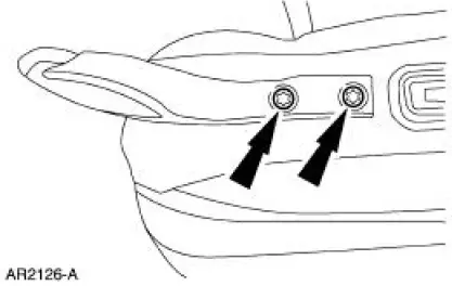
3. Remove the screws and the safety belt guide.
4. Remove the front seat headrest guide rod sleeve (610A16).
5. Release the J-clip.
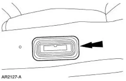
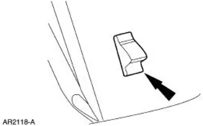
6. Remove the seat backrest latch handle knob.
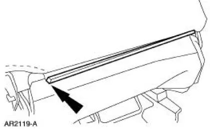
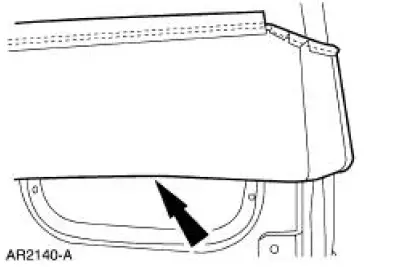
7. Pull the seat backrest trim cover upward.
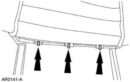
8. Remove the hog rings.
9. Remove the front seat backrest trim cover (64416) from the front seat backrest pad.
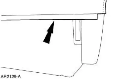
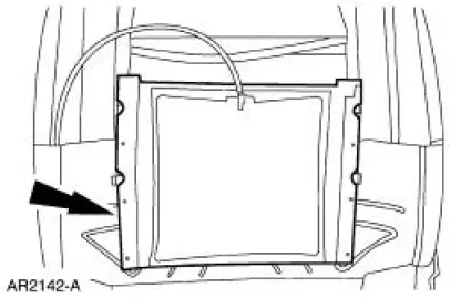
10. Release the front seat backrest frame (61018) from the front seat backrest foam pad.
Vehicles with standard power lumbar
11. Remove the seat backrest lumbar adjuster pad.
Vehicles with power bolster and lumbar
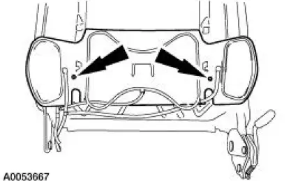
12. Remove the two screws and the seat backrest lumbar and bolster adjuster pad.
All vehicles
13. To assemble, reverse the disassembly procedure.
 Front Seat Cushion
Disassembly and Assembly
All vehicles
1. Remove the seat track. For additional information, refer to Seat Track
in this section.
2. Remove the seat backrest. For additional information, refer to ...
 Glass, Frames and Mechanisms
WINDOW REGULATOR ELECTRIC DRIVE
CURRENT DRAW
General Specifications
Torque Specifications
...
Other materials:
Bushing - Stabilizer Bar
Removal
CAUTION: Suspension fasteners are critical parts because they affect
performance of vital
components and systems and their failure can result in major service expense. A
new part with
the same part number or an equivalent part must be installed, if i ...
Principles of Operation
The vehicle has two module communications networks. The standard
corporate protocol (SCP) which
is an unshielded twisted pair cable (data bus plus, Circuit 914 [TN/OG] and
data bus minus, Circuit 915
[PK/LB]), and the international standards organization ...
Seat - Front Power
Removal and Installation
1. Remove the safety belt through the opening in the safety belt guide.
2. Move the seat forward.
3. Remove the bolt covers and remove the seat track bolts.
4. Move the seat rearward.
5. Remove the seat track nuts.
6. Move the ...
