Ford Mustang (1999-2004) Service Manual: Front Subframe - 3.8L Engine
Special Tool(s)
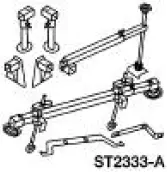 |
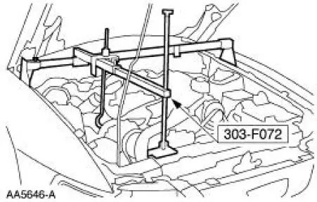
3-Bar Engine Support Kit 303-F072 |
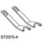 |
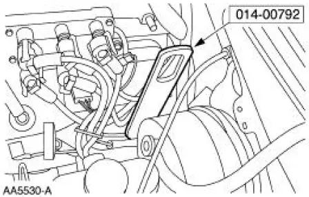
Lifting Bracket Set, Engine 303-D095 (D94L-6001-A) (014- 00792) |
Removal and Installation
All vehicles
1. Remove the steering gear. For additional information, refer to Section.
2. Remove the lower control arms. For additional information, refer to Section.
Vehicles with convertible top
3. Remove the front subframe support. For additional information, refer to Subframe Support- Convertible in this section.
Vehicles with hard top
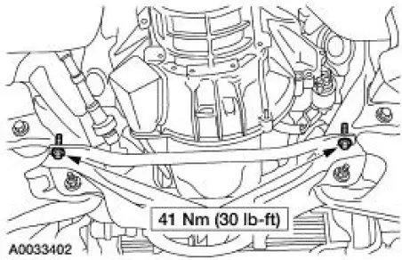
4. Remove the front subframe brace.
- Remove the bolts.
All vehicles
5. Lower the vehicle.
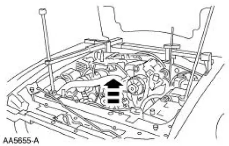
6. Install the special tool.
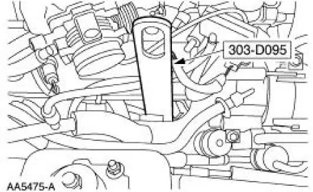
7. Install the special tool.
8. Install the special tool.
9. Raise and support the vehicle.
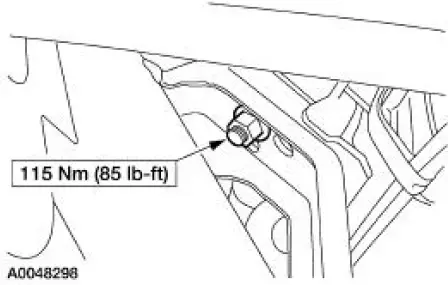
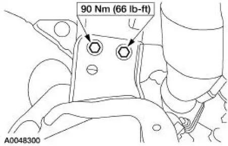
10. Remove the LH engine mount nut.
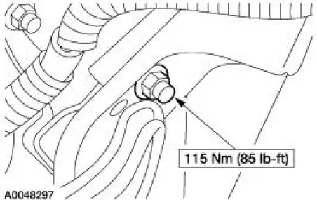
11. Remove the RH engine mount nut.
12. Lower the vehicle.
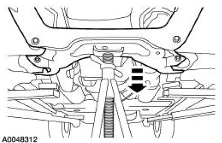
13. Using the special tool, raise and support the engine.
14. Raise the vehicle.
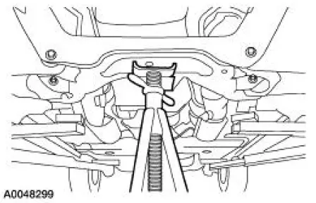
15. Support the front subframe.
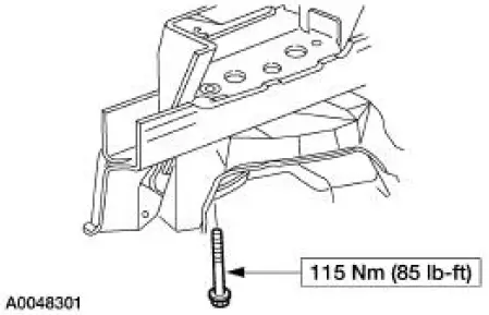
16. Remove the four front subframe lower bolts.
17. Remove the four front subframe upper bolts.
18. NOTE: Two technicians are needed to carry out this step.
Lower and remove the front subframe.
19. To install, reverse the removal procedure.
 Underbody Misalignment Check
Underbody Dimensions
1. Underbody dimensions tolerances are +- 3.175 mm (0.125 in). Reference
dimensions are not
controlled dimensions. Reference points are +- 4.76 mm (0.1875 in). All und ...
 Front Subframe - 4.6L (2V) Engine
Special Tool(s)
Support Bar, Engine
303-290-A
Lifting Bracket, Engine
303-D088 (D93P-6001-A2)
Removal and Installation
All vehicles
1. Remove the steering gear. For addit ...
Other materials:
Special Testing Procedures
The special tests are designed to aid the technician in diagnosing the
hydraulic and mechanical portion
of the transmission.
Engine Idle Speed Check
Refer to the Powertrain Control/Emissions Diagnosis (PC/ED) manual for
diagnosis and testing of the
eng ...
Engine (Diagnosis and Testing)
Special Tool(s)
Commercially Available
Leakdown Tester
Quick Disconnect Compression
Tester
134-R0212 or equivalent
Dial Indicator Gauge Adapter
303-007 (TOOL-6565-AB) or
equivalent
Dial Indicator Gauge with
Holdin ...
Ignition Switch Lock Cylinder - Non-Functional
Removal and Installation
1. NOTE: Make sure the front wheels are in the straight-ahead
position.
Disconnect the battery ground cable (14301) and wait at least one minute to
allow the depletion
of the restraint system backup power supply.
2. WARNING: To avo ...
