Ford Mustang (1999-2004) Service Manual: Front Subframe - 4.6L (2V) Engine
Special Tool(s)
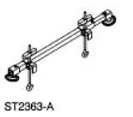 |
Support Bar, Engine 303-290-A |
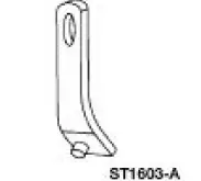 |
Lifting Bracket, Engine 303-D088 (D93P-6001-A2) |
Removal and Installation
All vehicles
1. Remove the steering gear. For additional information, refer to Section.
2. Remove the lower control arms. For additional information, refer to Section.
Vehicles with convertible top
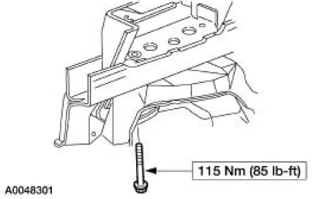
3. Remove the front subframe support. For additional information, refer to Subframe Support - Convertible in this section
Vehicles with hard top
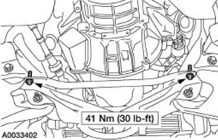
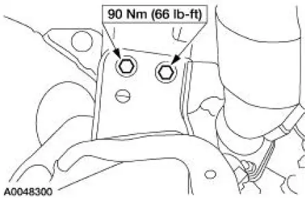
4. Remove the front subframe brace.
- Remove the bolts
All vehicles
5. Lower the vehicle.
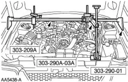
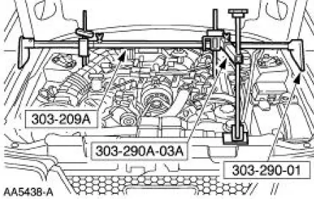
6. Install the special tool.
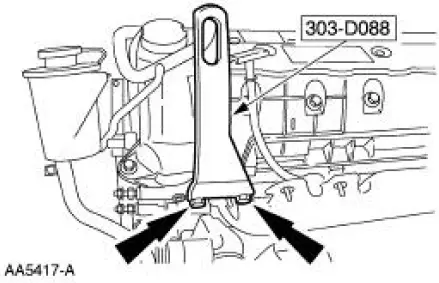
7. Install the special tool.
8. Raise and support the vehicle.
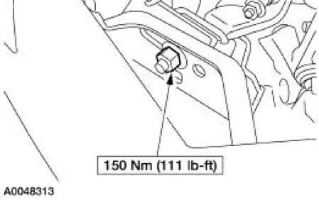
9. Remove the two engine mount nuts.
10. Lower the vehicle.
11. Using the special tool, raise and support the engine.
12. Raise the vehicle.
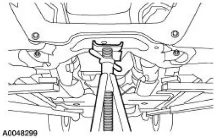
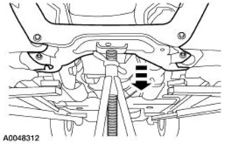
13. Support the front subframe.
14. Remove the four front subframe lower bolts.
15. Remove the four front subframe upper bolts.
16. NOTE: Two technicians are needed to carry out this step.
Lower and remove the front subframe.
 Front Subframe - 3.8L Engine
Special Tool(s)
3-Bar Engine Support Kit
303-F072
Lifting Bracket Set, Engine
303-D095 (D94L-6001-A) (014-
00792)
Removal and Installation
All vehicles
1. Remove the st ...
 Front Subframe - 4.6L (4V) Engine
Special Tool(s)
3-Bar Engine Support Kit
303-F072
Lifting Bracket, Engine
303-D088 (D93P-6001-A2)
Removal and Installation
All vehicles
1. Remove the steering gear. For a ...
Other materials:
Damper
Removal
CAUTION: Suspension fasteners are critical parts because they affect
performance of vital
components and systems and their failure can result in major service expense. A
new part with
the same part number must be installed if installation becomes nec ...
Geartrain
Power is transmitted from the torque converter to the Ravigneaux
geartrain components through the
input shaft and forward clutch cylinder.
The geartrain contains a Ravigneaux planetary set connected by
dual pinion gears.
By holding or driving ...
Accessories
For a complete listing of the accessories that are available for your
vehicle, please contact an authorized dealer or visit our online store at
Accessories.Ford.com (United States only).
Ford Custom Accessories are available for your vehicle through an
author ...
