Ford Mustang (1999-2004) Service Manual: Front Subframe - 4.6L (4V) Engine
Special Tool(s)
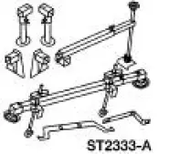 |
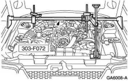
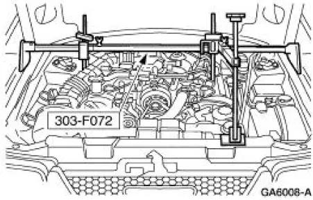
3-Bar Engine Support Kit 303-F072 |
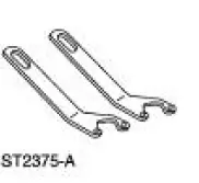 |
Lifting Bracket, Engine 303-D088 (D93P-6001-A2) |
Removal and Installation
All vehicles
1. Remove the steering gear. For additional information, refer to Section .
2. Remove the lower control arms. For additional information, refer to Section.
Vehicles with convertible top
3. Remove the front subframe support. For additional information, refer to Subframe Support- Convertible in this section.
Vehicles with hard top
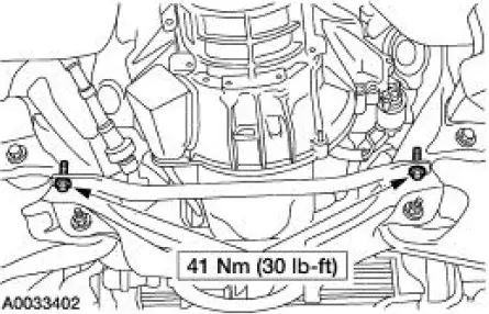
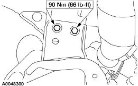
4. Remove the front subframe brace.
- Remove the bolts.
All vehicles
5. Lower the vehicle.
6. Install the special tool.
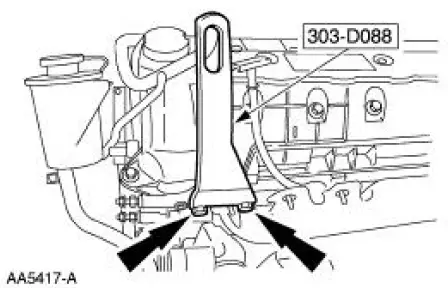
7. Install the special tool.
8. Raise and support the vehicle.
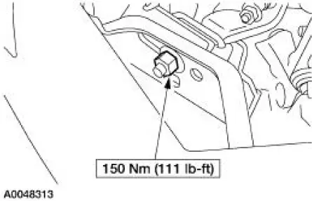
9. Remove the two engine mount nuts.
10. Lower the vehicle.
11. Using the special tool, raise and support the engine.
12. Raise the vehicle.
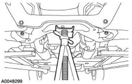
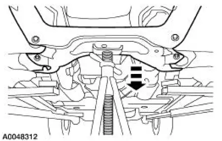
13. Support the front subframe.
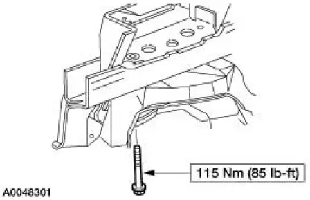
14. Remove the four front subframe lower bolts.
15. Remove the four front subframe upper bolts.
16. NOTE: Two technicians are needed to carry out this step.
Lower and remove the front subframe.
17. To install, reverse the removal procedure.
 Front Subframe - 4.6L (2V) Engine
Special Tool(s)
Support Bar, Engine
303-290-A
Lifting Bracket, Engine
303-D088 (D93P-6001-A2)
Removal and Installation
All vehicles
1. Remove the steering gear. For addit ...
 Rear Subframe
Removal and Installation
CAUTION: Suspension fasteners are critical parts because they affect
performance of vital
components and systems and their failure can result in major service expense. A
new ...
Other materials:
Tire Wear Chart
Wheel and tire NVH concerns are directly related to vehicle speed and are not
generally affected by
acceleration, coasting or decelerating. Also, out-of-balance wheel and tires can
vibrate at more than
one speed. A vibration that is affected by the engine ...
Runout Check - Brake Disc and Hub
Special Tool(s)
Brake Measurement Kit
134-R0199 or equivalent
Material
Item
Specification
High Temperature Nickel Anti-
Seize Lubricant
F6AZ-9L494-AA
ESE-M12A4-
A
CAUTION: The brake disc (1126) runout specification must ...
Installation
1. Install the intake manifold and gaskets, tighten the bolts in the sequence
shown.
2. NOTE: The O-ring is to be installed on the top of the thermostat.
Install the water thermostat and the O-ring.
Install a new O-ring as necessary.
3. Install the wa ...
