Ford Mustang (1999-2004) Service Manual: Countershaft Bearing
Special Tool(s)
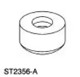 |
Bearing Replacer 308-061 (T77J-7025-L) |
 |
Front Bearing Replacer 308-062 (T77J-7025-M) |
 |
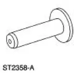
Mainshaft Front Bearing Replacer 308-081 (T82T-7003-DH) |
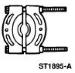 |
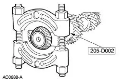
Pinion Bearing Cone Remover 205-D002 (D79L-4621-A) or Equivalent |
 |
Pinion Bearing Cone Replacer 205-011 (T57L-4621-B) |
 |
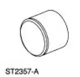
Remover and Replacer Tube 308-024 (T75L-7025-B) |
 |
Remover and Replacer Tube 308-052 (T77J-7025-B) |
Disassembly
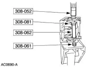
1. Using the special tool and a press, remove the countershaft bearing assembly (7F431).
2. CAUTION: Failure to correctly support the case (7005) during bearing race removal will result in permanent distortion of the case.
NOTE: Remove the front countershaft bearing race only if damaged or worn.
Using the special tools and a press, remove the bearing race and the countershaft front bearing seal (7693).
Assembly
NOTE: Position the countershaft in the transmission case before installing the rear countershaft bearing.
1. Install the countershaft front bearing seal on the bearing race.
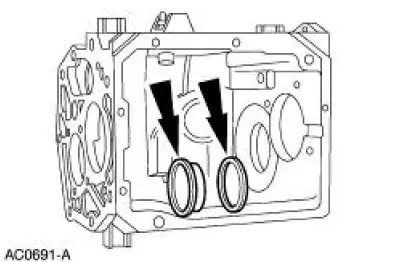
2. Coat the outside diameter of the bearing race with sealer.
- Use Threadlock and Sealer E0AZ-19554-AA or equivalent meeting Ford specification WSK-M2G351-5A.
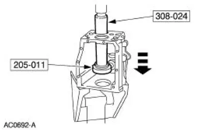
3. CAUTION: Failure to correctly support the case during bearing race installation will result in permanent distortion of the case.
Using the special tools and a press, install the bearing race.
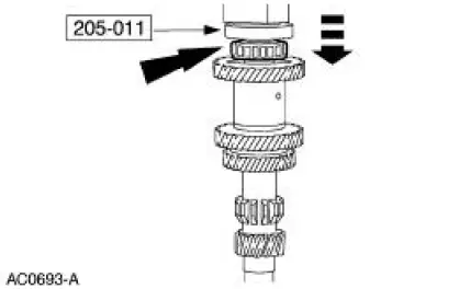
4. Using the special tool and a press, install the front countershaft bearing.
 Output Shaft
Special Tool(s)
Pinion Bearing Cone Remove
205-D002 (D79L-4621-A) or
Equivalent
Spiral Snap Ring Replacer
308-096 (T85P-7025-A)
Disassembly
1. Using the special tool a ...
 Synchronizers
Disassembly
NOTE: This procedure applies to all synchronizer assemblies
(7124). The synchronizers are slightly
different in design. Notation is made where procedural differences occur.
1. On the ...
Other materials:
Pinpoint Test H: LFC 32/DTC B1932 - Driver Air Bag Circuit Resistance High
Normal Operation
The restraints control module (RCM) monitors the resistance for the
driver air bag ignitor by measuring
the resistance between pins 3 and 4. If the RCM detects high resistance
between these pins, it will
store a diagnostic trouble code ...
Spark Plugs
Removal and Installation
1. Remove the ignition coil-on-plug. For additional information, refer to
Ignition Coil-On-Plug in this
section.
2. NOTE: Use compressed air to remove any foreign material from the
spark plug well before
removing the spark plu ...
Installation
All vehicles
CAUTION: After installing the urethane installed windshield,
the vehicle should not be
driven until the urethane adhesive has cured. The curing time at
temperatures above 13C (55
F) and relative humidity above 50% is 12-24 hours (Refer ...
