
Ford Mustang (1999-2004) Service Manual: Fuel Charging And Controls
The fuel injection supply manifold (9F792):
- delivers fuel to the fuel injector.
- receives fuel from the fuel supply line.
The throttle body (9E926):
- controls air supply to the upper intake manifold (9424) by positioning the throttle plate.
- connects the accelerator cable (9A758) and the speed control actuator cable (9A825) (if equipped) to the throttle lever.
- is not adjustable.
- cannot be cleaned.
The fuel injector (9F593):
- is electrically operated by the powertrain control module (PCM) (12A650).
- has an internal solenoid that opens a needle valve to inject fuel into the lower intake manifold.
- atomizes the fuel as the fuel is delivered.
- is deposit-resistant. Do not clean.
The fuel pressure relief valve (9H321):
- is used to inspect and relieve fuel pressure.
Fuel Charging Wiring Connections
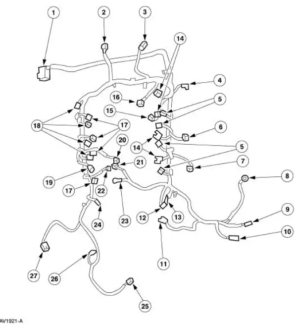
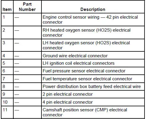
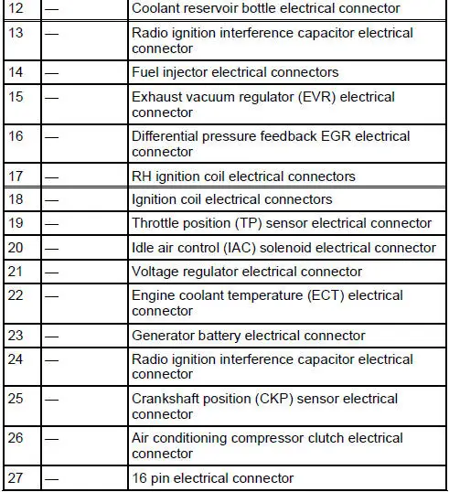
Fuel Charging And Controls
Refer to the Powertrain Control/Emissions Diagnosis (PC/ED) manual.
Idle Speed Adjustment
Powertrain Control/Emissions Diagnosis (PC/ED) manual
 Fuel Charging and Controls - 4.6L (2V)
General Specifications
Torque Specifications
...
 Throttle Body
Removal
WARNING: Do not smoke or carry lighted tobacco or open flame of any
type when
working on or near any fuel related components. Highly flammable mixtures are
always present
and may be ignited. ...
Other materials:
Sun visors
Slide-On-Rod
Rotate the visor toward the side
window and extend it rearward for
extra sunlight coverage.
Retract the visor before moving it
back toward the windshield and
storing it.
Illuminated Visor Vanity Mirror
Lift the cover to switch on the lamp.
Flex ...
Inspection and Verification
1. Verify customer concern by running the engine.
2. Inspect the drive belt for chunking, fraying and wear.
3. Check the drive belt for correct routing.
Drive Belt Cracking/Chunking/Wear
V Ribbed Serpentine Drive Belt With Cracks Across Ribs
The accessory ...
Removal
1. Disconnect the battery ground cable.
2. Remove the air cleaner outlet tube. For additional information, refer to
Section.
3. Remove the radiator sight shield.
4. Install the special tool.
5. Using the special tools, support the engine.
6. Raise and sup ...
