Ford Mustang (1999-2004) Service Manual: Throttle Body
Removal
WARNING: Do not smoke or carry lighted tobacco or open flame of any type when working on or near any fuel related components. Highly flammable mixtures are always present and may be ignited. Failure to follow these instructions may result in personal injury.
CAUTION: The throttle body bore and plate area have a special coating and cannot be cleaned.
1. Remove the air cleaner outlet tube (9B659). For additional information, refer to Section.
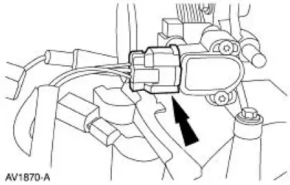
2. Disconnect the throttle position (TP) sensor electrical connector.
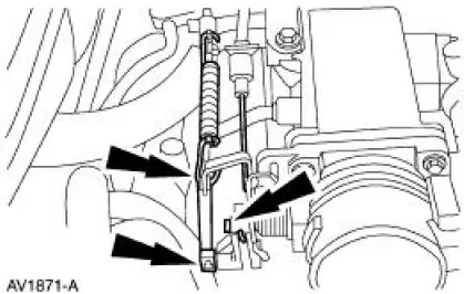
3. Disconnect the accelerator controls.
- Disconnect the accelerator cable (9E926).
- Disconnect the speed control cable (9A825).
- Disconnect the return spring.
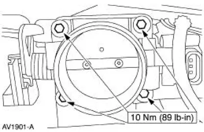
4. NOTE: Discard the throttle body gasket.
Remove the throttle body.
- Remove the bolts.
- Remove the throttle body.
Installation
1. To install, reverse the removal procedure.
 Fuel Charging And Controls
The fuel injection supply manifold (9F792):
delivers fuel to the fuel injector.
receives fuel from the fuel supply line.
The throttle body (9E926):
controls air supply to the upper intake manifo ...
 Fuel Injectors
Removal
WARNING: Do not smoke or carry lighted tobacco or open flame of any
type when
working on or near any fuel related components. Highly flammable mixtures are
always present
and may be ignited. ...
Other materials:
Radiator
Removal and Installation
1. Drain the coolant. For additional information, refer to Supercharger
Cooling System Draining,
Filling and Bleeding in this section.
2. NOTE: RH is shown LH is similar.
Disconnect the two coolant hoses.
3. Remove the bolts an ...
Paint Codes
The first set of paint code letters/numbers listed indicate the vehicle
primary body color. The second
set of paint code letters/numbers listed (if applicable) indicate a two-tone or
accent body color.
B7 - Zinc Yellow (clear coat)
CX - Dark Shadow Gray ...
Latch - Front Seat Backrest
Removal
NOTE: The power seat backrest adjuster assembly must be installed as a
new unit. Repair of the
power seat backrest adjuster assembly components is not acceptable and
should not be attempted.
1. Remove the two screws and the seat backrest latch ...
