Ford Mustang (1999-2004) Service Manual: Fuel Charging Wiring Harness
Removal and Installation
WARNING: Do not smoke or carry lighted tobacco or open flame of any type when working on or near any fuel related components. Highly flammable mixtures are always present and can ignite. Failure to follow these instructions can result in personal injury.
1. Disconnect the battery ground cable.
2. Remove the exhaust gas recirculation (EGR) valve and the exhaust manifold to EGR valve tube. For additional information, refer to Section.
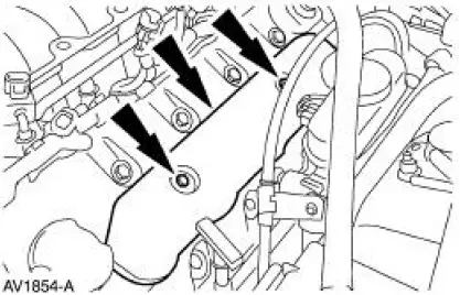
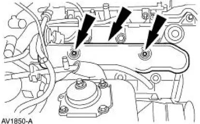
3. Remove the bolts and the LH ignition coil cover.
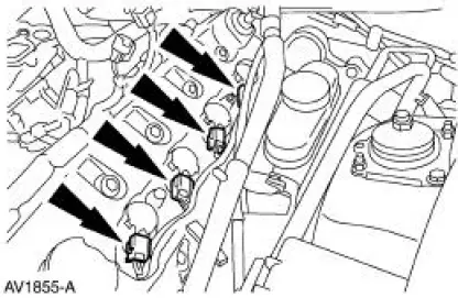
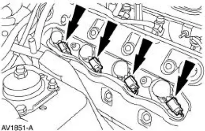
4. Disconnect the LH ignition coil electrical connectors.
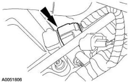
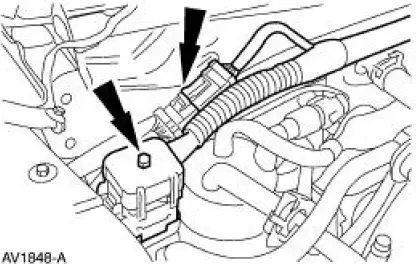
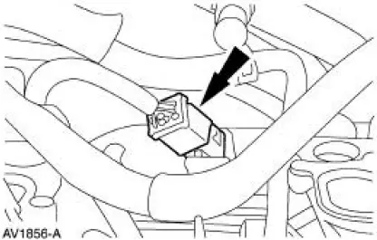
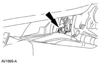
5. Disconnect the barometric pressure (BARO) sensor electrical connector.
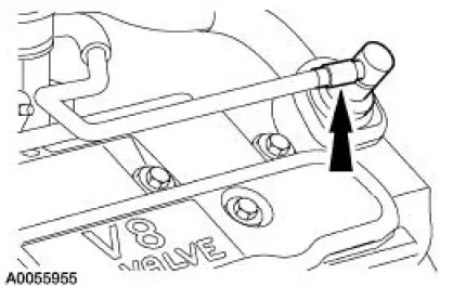
6. Remove the PCV valve.
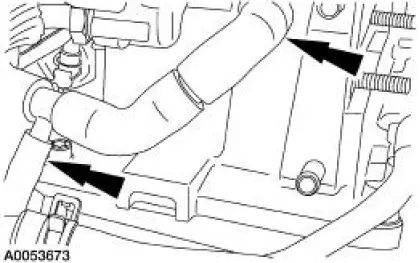
7. Disconnect and remove the PCV hose.
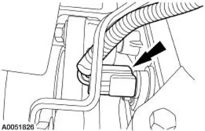
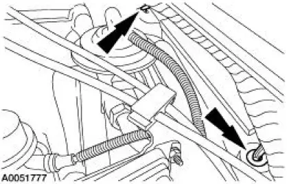
8. Disconnect the camshaft position (CMP) sensor electrical connector.
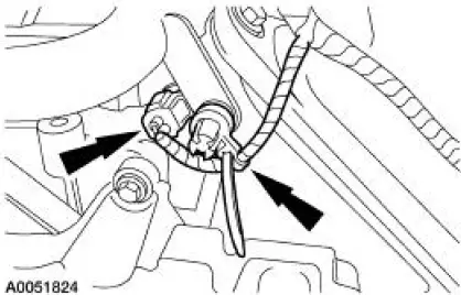
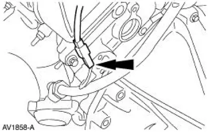
9. Disconnect the engine coolant temperature (ECT) sensor electrical connector and unclip the harness from the stud.
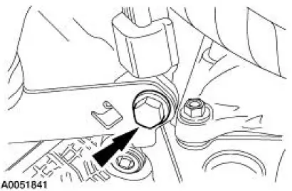
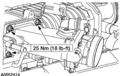
10. Remove the fuel charging wiring harness bracket bolt.
11. Disconnect the following:
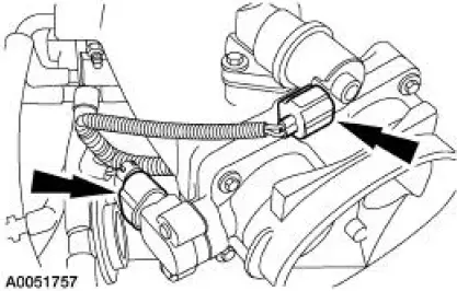
- The 42-pin engine bulkhead electrical connector.
- The 16-pin electrical connector.
12. Separate the wiring harness from the dash panel.
13. Remove the air cleaner outlet pipe. For additional information, refer to Section.
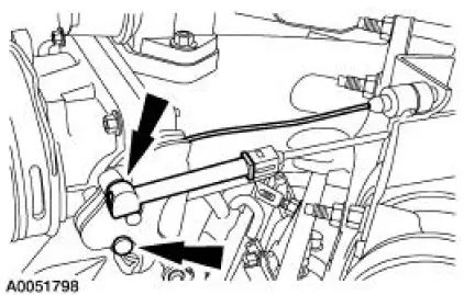
14. Disconnect the throttle position (TP) and the idle air control (IAC) valve electrical connectors.
15. Disconnect the accelerator cable, and if equipped, the speed control cable.
16. Remove the nuts and the throttle body spacer assembly.
17. Remove the bolts and the RH ignition coil cover.
18. Disconnect the RH ignition coil electrical connectors.
19. Disconnect the transmission main control harness electrical connector.
20. Raise and support the vehicle. For additional information, refer to Section.
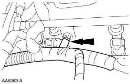
21. Disconnect the RH heated oxygen sensor (HO2S) electrical connector.
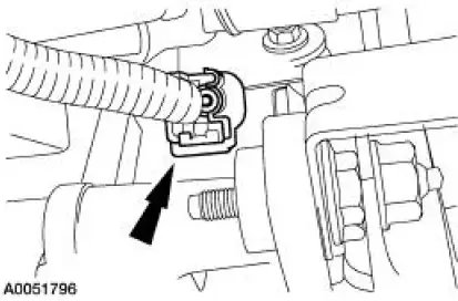
22. Disconnect the crankshaft position (CKP) sensor electrical connector.
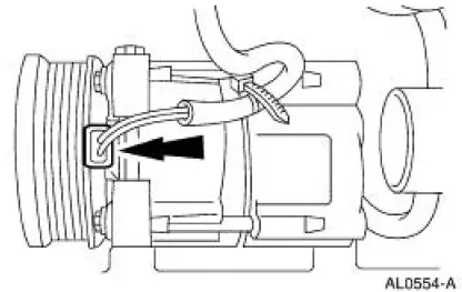
23. Disconnect the air conditioning compressor electrical connector.
24. Unclip the harness from the bracket.
25. Lower the vehicle.
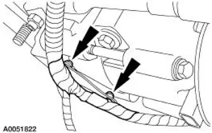
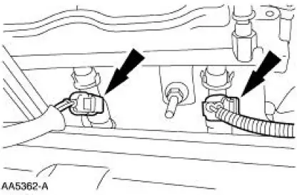
26. NOTE: LH side shown, RH side similar.
Disconnect the two radio ignition interference capacitor electrical connectors.
27. Disconnect the eight fuel injectors
28. Separate the harness from the fuel supply manifold studs in four places and remove the fuel charging wiring harness from the vehicle.
29. To install, reverse the removal procedure.
 Throttle Body
Removal and Installation
WARNING: Do not smoke or carry lighted tobacco or open flame of any
type when
working on or near any fuel related components. Highly flammable mixtures are
always present
an ...
 Fuel Injection Supply Manifold and Fuel Injector
Material
Item
Specification
SAE 5W-20 Premium Synthetic
Blend Motor Oil
XO-5W20-QSP
WSS-M2C153-
H
Removal and Installation
WARNING: Do not smoke or carry lighted tobacco or op ...
Other materials:
Rear Wheel Bearing and Axle Shaft Oil Seal
Special Tool(s)
Adapter for 303-224
205-153 (T80T-4000-W)
Installer, Axle Shaft Bearing
205-124 (T78P-1225-A)
Installer, Rear Axle Oil Seal
205-390 (T97T-1177-B)
Remover, Axle Bearing
205-219 (T85L-1225-AH)
S ...
Inspection and Verification
1. Verify the customer concern is with the evaporative emission (EVAP)
system.
2. Visually inspect for the following obvious signs of mechanical damage.
Visual Inspection Chart
Mechanical
Fuel filler cap
EVAP test port
...
Installation
Lift cylinder
1. NOTE: Be sure that each fitting is installed in the correct position on
the folding top hydraulic
component.
NOTE: Make sure that the tetra seal is installed in the bottom of each of the
folding top
hydraulic cylinder ports before attaching ...
