Ford Mustang (1999-2004) Service Manual: Fuel Injectors
Material
| Item | Specification |
| SAE 5W-20 Premium Synthetic Blend Motor Oil XO-5W20-QSP or equivalent | WSS-M2C153- H |
Removal and Installation
WARNING: Do not smoke or carry lighted tobacco or open flame of any type when working on or near any fuel related components. Highly flammable mixtures are always present and may ignite. Failure to follow these instructions may result in personal injury.
WARNING: Fuel in the fuel system remains under high pressure even when the engine is not running. Before working on or disconnecting any of the fuel lines or fuel system components, the fuel pressure must be relieved. Failure to follow these instructions may result in personal injury
1. Remove the supply manifold. For additional information, refer to Supply Manifold in this section.
2. Remove the six fuel injectors from the supply manifold.
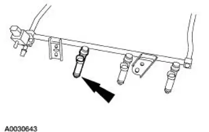
3. CAUTION: The retaining clip must be in the upper groove on the injector or the injector may become loose.
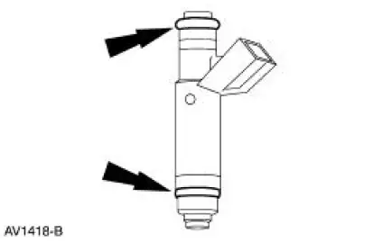
NOTE: Inspect the two O-rings from each fuel injector. Install new O-rings as needed.
NOTE: Lubricate the new O-rings with clean engine oil to aid installation.
To install, reverse the removal procedure.
 Throttle Body
Removal and Installation
WARNING: Do not smoke or carry lighted tobacco or open flame of any
type when
working on or near any fuel related components. Highly flammable mixtures are
always present
an ...
 Fuel Charging Wiring Harness
Removal and Installation
WARNING: Do not smoke or carry lighted tobacco or open flame of any
type when
working on or near any fuel related components. Highly flammable mixtures are
always present
an ...
Other materials:
Ignition switch
A. Off: The ignition is off.
Note: When you switch the ignition off and leave your vehicle, do not
leave your key in the ignition. This could cause your vehicle battery to
lose charge.
B. Accessory: Allows the electrical accessories such as the radio to
ope ...
Input Shaft and Bearing
Special Tool(s)
Plate, Bearing/Oil Seal
205-090 (T75L-1165-B)
Puller, Bearing
205-D064 (D84L-1123-A)
Installer, Drive Pinion Bearing
Cone
205-004 (T53T-4621-B)
Adapter Set, Step Plate
205-DS011 (D80L-630 ...
Manual Control Lever Shaft and Seal
Special Tool(s)
Installer, Shift Shaft Fluid Seal
307-050 (T74P-77498-A)
Alignment Gauge, TR Sensor
307-351 (T97L-70010-A)
Removal
1. Drain the transmission fluid and remove the fluid pan and filter. For
additional information, ...
