Ford Mustang (1999-2004) Service Manual: Fuel Injectors
Removal
WARNING: Do not smoke or carry lighted tobacco or open flame of any type when working on or near any fuel related components. Highly flammable mixtures are always present and may be ignited. Failure to follow these instructions may result in personal injury.
WARNING: Fuel in the fuel system remains under high pressure even when the engine is not running. Before working on or disconnecting any of the fuel lines or fuel system components, the fuel pressure must be relieved. Failure to follow these instructions may result in personal injury.
1. Relieve the fuel pressure. For additional information, refer to Section.
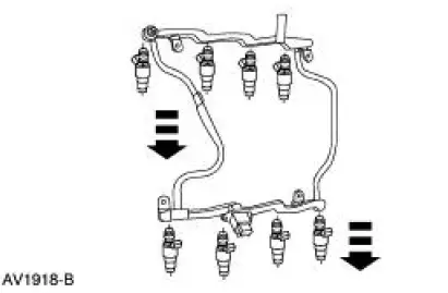
2. Remove the supply manifold. For additional information, refer to Fuel Injection Supply Manifold in this section.
3. Remove the fuel injectors from the supply manifold.
Installation
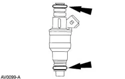
1. NOTE: Lubricate the new O-rings with Super Premium SAE 10W-30, XO-10W30-DSP or equivalent meeting Ford specification WSS-M2C153-G, to aid installation.
Inspect the two O-rings on each fuel injector. Install new O-rings if necessary.
2. Install the fuel injectors onto the supply manifold.
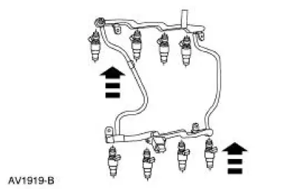
3. Install the fuel supply manifold.
 Throttle Body
Removal
WARNING: Do not smoke or carry lighted tobacco or open flame of any
type when
working on or near any fuel related components. Highly flammable mixtures are
always present
and may be ignited. ...

Other materials:
Piston - Pin Connecting Rod, Floating Pin
Material
Item
Specification
SAE 5W-20 Premium Synthetic
Blend Engine Oil
XO-5W20-QSP
WSS-M2C153-
H
Disassembly
1. Remove the clips.
2. Remove the piston pin from the piston and connecting rod assembly.
3. Remove the connecting rod ...
Daytime Running Lamps (DRL) (Diagnosis and Testing)
Refer to Wiring Diagrams Cell 97 , Daytime Running Lamps for schematic
and connector information.
Special Tool(s)
73III Automotive Meter or
equivalent
105-R0057
Principles of Operation
Daytime Running Lamps (DRL)
The daytime running lamp ...
Clearing all MyKeys
You can clear all MyKeys within the same key cycle as you created the
MyKey. If you switch your ignition off, however, you will need to use an
admin key to clear your MyKeys.
Note: When you clear your MyKeys, you remove all restrictions and
return all MyKeys ...
