Ford Mustang (1999-2004) Service Manual: A/C Compressor and Clutch Assembly
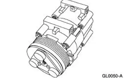
NOTE: Internal A/C compressor components are not serviced separately. The FS-10 A/C compressor is serviced only as an assembly. The A/C clutch pulley, A/C clutch field coil (19D798) and the shaft seal are serviceable.
The FS-10 A/C compressor has the following characteristics:
- A ten-cylinder swashplate design utilizing the tangential design mount.
- A one-piece lip-type seal (installed from the front of the A/C compressor) is used to seal it at the shaft opening in the assembly.
- Five double-acting pistons operate within the cylinder assembly. The pistons are actuated by a swashplate that converts the rotating action of the shaft to a reciprocating force.
- Reed-type discharge valves are located between the cylinder assembly and the head at each end of the A/C compressor.
- The A/C compressor uses PAG oil, or equivalent. This oil contains special additives required for the A/C compressor.
- The A/C compressor oil from vehicles equipped with an FS-10 A/C compressor may have some dark colored streaking while maintaining a normal oil viscosity. This is normal for the A/C compressor and is caused by break-in wear of the piston rings.
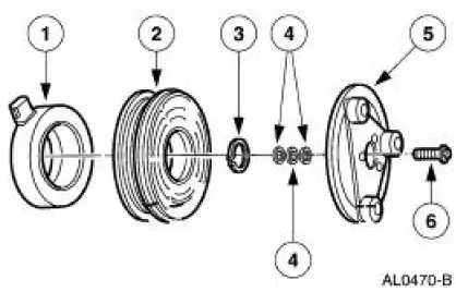
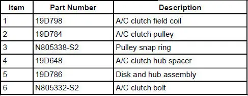
The magnetic A/C clutch has the following characteristics:
- It drives the compressor shaft.
- When the battery positive voltage (B+) is applied to the A/C clutch field coil, the clutch plate and hub assembly is drawn toward the A/C clutch pulley.
- The magnetic force locks the clutch plate and hub assembly and the A/C clutch pulley together as one unit, causing the compressor shaft to rotate.
- When (B+) is removed from the A/C clutch field coil, springs in the clutch plate and hub assembly move the clutch plate away from the A/C clutch pulley.
 Air Conditioning (Description and Operation)
The A/C refrigerant system is a clutch cycling orifice tube type. The system
components are:
A/C compressor (19703)
A/C clutch (2884)
A/C condenser core (19712)
A/C evaporator core (19860)
suct ...
 A/C Compressor Pressure Relief Valve
An A/C compressor pressure relief valve is incorporated into the compressor
A/C manifold and tube to:
relieve unusually high refrigerant system discharge pressure buildups.
For specifications
...
Other materials:
Runout Check - Brake Disc and Hub
Special Tool(s)
Brake Measurement Kit
134-R0199 or equivalent
Material
Item
Specification
High Temperature Nickel Anti-
Seize Lubricant
F6AZ-9L494-AA
ESE-M12A4-
A
CAUTION: The brake disc (1126) runout specification must ...
Installation
1. Install the upper intake manifold gasket.
2. Install the intake manifold and bolts in the sequence shown.
3. Install the PCV valve-to-intake manifold tube.
4. Connect the vacuum hoses and the electrical connector to the EGR vacuum
regulator soleno ...
Manual Transaxle/Transmission - T5OD
General Specifications
Torque Specifications
...
