Ford Mustang (1999-2004) Service Manual: Fuel Pressure Sensor
Material
| Item | Specification |
| Super Premium SAE 5W-20 Motor Oil XO-5W20-DSP or equivalent | WSS-M2C914- A |
Removal
WARNING: Do not smoke or carry lighted tobacco or open flame of any type when working on or near any fuel related components. Highly flammable mixtures are always present and may be ignited. Failure to follow these instructions may result in personal injury.
WARNING: Fuel in the fuel system remains under high pressure even when the engine is not running. Before working on or disconnecting any of the fuel lines or fuel system components, the fuel system pressure must be relieved. Failure to follow these instructions may result in personal injury.
Mach I
1. Remove the air intake scoop. For additional information, refer to Section.
All engines
2. Relieve the fuel pressure. For additional information, refer to Section.
3. NOTE: The 4.6L (4V) Cobra engine is shown, the other engines are similar.
Disconnect the connector and the vacuum line.
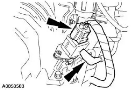
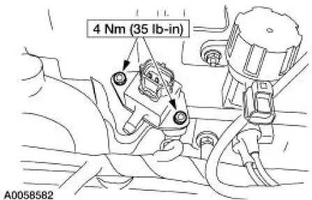
4. Remove the bolts and the sensor.
Installation
1. Inspect the O-rings, and install new O-rings if necessary.
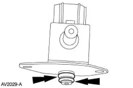
2. NOTE: Lubricate the new O-rings with clean engine oil to aid installation.
To install, reverse the removal procedure.
Supercharger Bypass Vacuum Solenoid
Removal and Installation
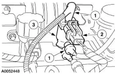
1. Remove the supercharger bypass vacuum solenoid.
1. Disconnect the vacuum hoses.
2. Disconnect the electrical connector.
3. Unclip the supercharger bypass vacuum solenoid from the vacuum accessory bracket.
2. To install, reverse the removal procedure.
 Clutch Pedal Position (CPP) Switch
Removal
1. Disconnect the battery ground cable. For additional information,
refer to Section.
2. Disconnect the connector.
3. Remove the bolt and the clutch pedal position (CPP) switch.
In ...

Other materials:
Transmission Electronic Control System
The powertrain control module (PCM) and its input/output network
control the following transmission
operations:
Shift timing
Line pressure (shift feel)
Torque converter clutch
The transmission control is separate from the engine control s ...
Gear (Removal and Installation)
Special Tool(s)
Teflon Seal Replacer Set
211-D027 (D90P-3517-A) or
Equivalent
Tie Rod End Remover
211-001 (TOOL-3290-D)
Removal
1. Turn the steering wheel as necessary to position the wheels in the
straight-ahead position. Do
not loc ...
Disc and Pressure Plate - 4.6L (4V) Engine
Special Tool(s)
Clutch Aligner
308-020 (T74P-7137-K)
Material
Item
Specification
Premium Long Life Grease
XG-1-C
ESA-M1C75-B
1. Disconnect the battery ground cable. For additional information, refer to
Section.
2. Remove t ...
