Ford Mustang (1999-2004) Service Manual: Electronic Engine Controls
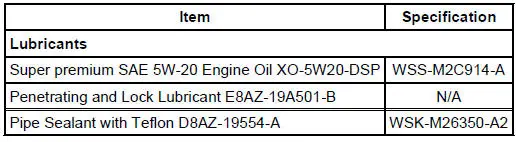
General Specifications
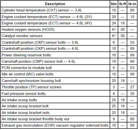
Torque Specifications
- Electronic Engine Controls (Description and Operation)
- Electronic Engine Controls - Cobra
- Temperature and Manifold Absolute Pressure (T-MAP) Sensor - Cobra
- Camshaft Position (CMP) Sensor - 3.8L
- Camshaft Position (CMP) Sensor - 4.6L
- Intake Manifold Runner Control (IMRC) Actuator - 3.8L
- Crankshaft Position (CKP) Sensor - 3.8L
- Crankshaft Position (CKP) Sensor - 4.6L
- Powertrain Control Module (PCM)
- Throttle Position (TP) Sensor
- Idle Air Control (IAC) Valve - 3.8L
- Idle Air Control (IAC) Valve - 4.6L (2V)
- Idle Air Control (IAC) Valve - Cobra
- Idle Air Control (IAC) Valve - Mach I
- Cylinder Head Temperature (CHT) Sensor - 3.8L
- Engine Coolant Temperature (ECT) Sensor - 4.6L (2V)
- Engine Coolant Temperature (ECT) Sensor - Cobra
- Engine Coolant Temperature (ECT) Sensor - Mach I
- Mass Air Flow (MAF) Sensor - 3.8L
- Mass Air Flow (MAF) Sensor - 4.6L (2V)
- Mass Air Flow (MAF) Sensor - Cobra
- Mass Air Flow (MAF) Sensor - Mach I
- Heated Oxygen Sensor (HO2S)
- Catalyst Monitor Sensor
- Clutch Pedal Position (CPP) Switch
- Fuel Pressure Sensor
- Supercharger Bypass Vacuum Solenoid - Actuator
 Evaporative Emission Test Port
Removal and Installation
1. Disconnect the pin-type retainer.
2. Raise and support the vehicle. For additional information, refer to
Section.
3. Remove the RH front wheel. For additional informa ...
 Electronic Engine Controls (Description and Operation)
The electronic engine controls consist of the following:
powertrain control module (PCM)
throttle position (TP) sensor
idle air control (IAC) valve
engine coolant temperature (ECT) sens ...
Other materials:
Pulley - CII Pump
Special Tool(s)
Pump Pulley Installer
211-009 (T65P-3A733-C)
Pump Pulley Remover
211-016 (T69L-10300-B)
Removal
1. Remove the drive belt.
2. Using the special tool, remove the pulley.
Installation
1. Using the special tool, instal ...
Pinpoint Tests - OSC Equipped Vehicles
Special Tool(s)
Breakout Box, EEC-V Control
System
418-049 (T94L-50-EEC-V) or
equivalent
MLP-TR Cable
418-F107 (007-00111) or
equivalent
Worldwide Diagnostic System
(WDS)
418-F224
New Generation STAR (NGS)
T ...
Accessory Drive - Cobra
Component Locations -Supercharger Accessory Drive
Component Location -Accessory Drive
...
