
Ford Mustang (1999-2004) Service Manual: Assembly
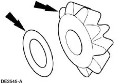
1. Lubricate the differential side gear thrust washers and the differential side gear journals, and assemble the washers to the gears.
- Use SAE 80W-90 Premium Rear Axle Lubricant XY-80W90-QL or equivalent meeting Ford specification WSP-M2C197-A.
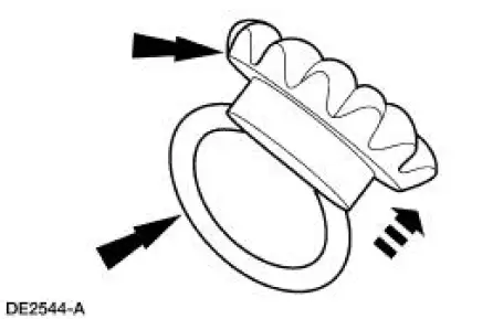
2. Lubricate the differential pinion thrust washers and the differential pinion gears, and assemble the washers to the gears.
- Use SAE 80W-90 Premium Rear Axle Lubricant XY-80W90-QL or equivalent meeting Ford specification WSP-M2C197-A.
3. Position the differential side gear and thrust washer assemblies in the differential case.
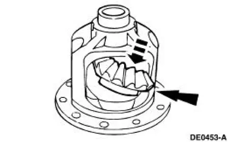
4. Engage the differential pinion gears with the differential side gears and rotate the pinion gears to align with the differential pinion shaft bore.
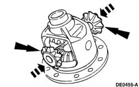
5. Insert the differential pinion shaft.
- Align the hole in the differential pinion shaft with the hole in the differential case.
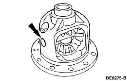
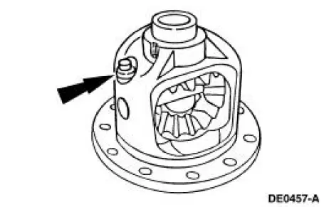
6. NOTE: If a new bolt is unavailable, coat the original bolt threads with Threadlock and Sealer EOAZ-19554-AA or equivalent meeting Ford specifications WSK-M2G351-A5 prior to installation.
Install a new bolt finger-tight.
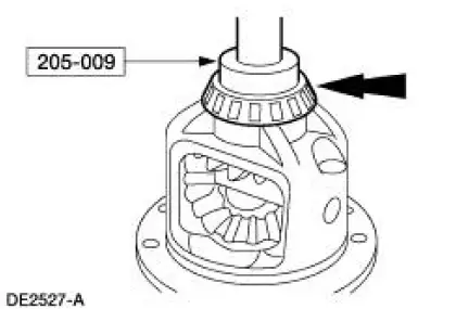
7. Using the special tool, install the new differential bearings, if removed.
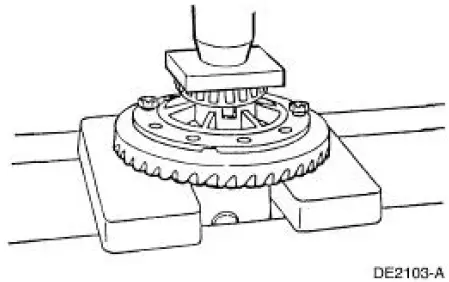
8. Position the ring gear and the differential case. Align the bolt holes by starting two bolts through the holes in the differential case and the ring gear. Press the ring gear on the differential case.
9. Install the bolts.
- Apply Stud and Bearing Mount EOAZ-19554-BA or equivalent meeting Ford specification WSK-M2G349-A1 to the bolt threads.
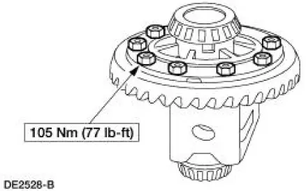
10. Install the differential case. For additional information, refer to Differential Case in this section.
 Disassembly
1. Remove the differential assembly from the differential housing. For
additional information, refer
to Differential Case in this section.
2. Remove the bolts.
3. CAUTION: Do not damage the thread ...
 Rear Drive Axle/Differential - Ford 8.8-Inch Ring Gear
General Specifications
Torque Specifications
Description
Nm
lb-ft
lb-in
Bolt retaining the differential pinion shaft to the
differential case
30
22
-
Bolt retaining t ...
Other materials:
Installation
CAUTION: The upper suspension arm and bushing nuts must be tightened
with the
suspension at curb height. Failure to do so can result in bushing failure,
resulting in poor ride
and handling.
NOTE: If installing a new upper suspension arm and bushing, mark the ...
Differential Housing Cover
Removal
1. Raise and support the vehicle.
2. NOTE: Empty the lubricant into a clean container for reuse.
Remove the differential housing cover (4033).
1. Remove the 10 bolts and drain the lubricant from the differential
housing (4010).
2. Remove the d ...
Removal
1. CAUTION: The vehicle must be on level ground and at curb height.
Mark the rear shock absorbers relative to their protective sleeve.
During installation, raise the suspension to this reference mark before
tightening the
suspension component fasteners.
...
