Ford Mustang (1999-2004) Service Manual: Gear (Removal and Installation)
Special Tool(s)
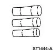 |
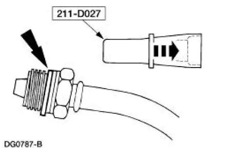
Teflon Seal Replacer Set 211-D027 (D90P-3517-A) or Equivalent |
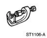 |
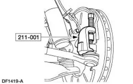
Tie Rod End Remover 211-001 (TOOL-3290-D) |
Removal
1. Turn the steering wheel as necessary to position the wheels in the straight-ahead position. Do not lock the steering column.
2. Raise and support the vehicle.
3. Remove the front wheels and tires.
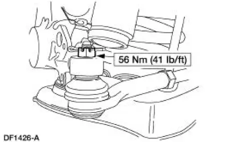
4. Remove the cotter pin and nut. Discard the cotter pin.
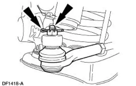
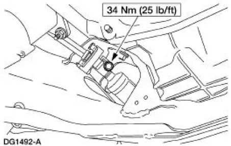
5. Using the special tool, disconnect the tie-rod end.
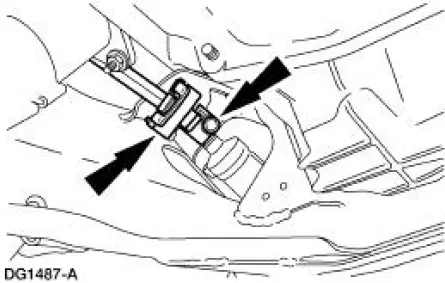
6. Rotate the steering column intermediate shaft as necessary to access the pinch bolt. Remove and discard the pinch bolt.
7. Lower the vehicle.
8. Turn the steering wheel back to the straight-ahead position. Turn the ignition key to the locked position.
9. CAUTION: Do not rotate the steering wheel when the lower steering column shaft is disconnected, or damage to the air bag sliding contact will result.
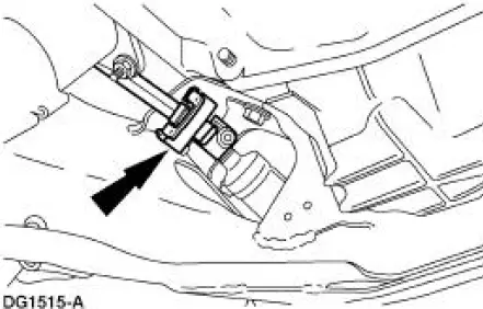
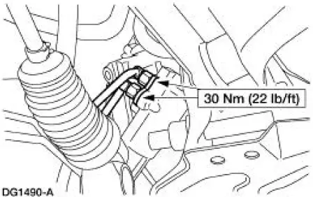
Disconnect the steering column intermediate shaft coupling (3A525).
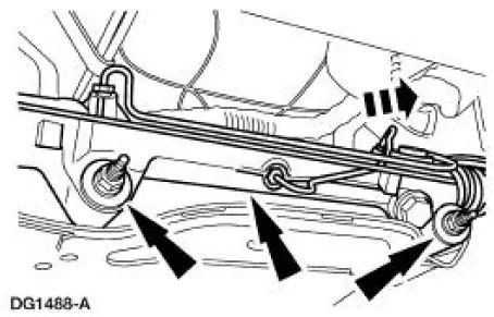
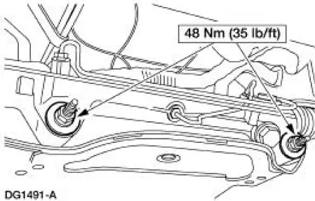
10. Remove the nuts, washers and bolts. Position the steering gear (3504) forward.
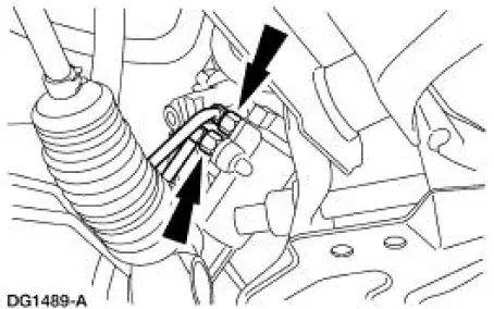
11. Disconnect the power steering hoses. Remove and discard the seal rings.
- Plug or cap the power steering hoses and steering gear ports to prevent damage and the entry of foreign material.
12. Remove the steering gear.
Installation
1. To install, reverse the removal procedure.
- Using the special tool, install a new seal ring.
- Install a new pinch bolt.
2. Fill and leak check the power steering system.
 Cooler - Fluid
Removal
1. Raise and support the vehicle.
2. Disconnect the power steering hoses.
3. Remove the bolt and routing bracket.
4. Remove the bolts and the power steering fluid cooler.
Installatio ...
 Gear (Disassembly and Assembly)
Special Tool(s)
Head Mounting Fixture
303-D041 (D83L-500-B1) or
Equivalent
Inner Tie Rod Socket Tool
211-D025 (D90P-3290-A) or
Equivalent
Steering Gear Holding Fixtur ...
Other materials:
Principles of Operation
Power Window Control
NOTE: Battery power and ground must be removed before disconnecting the
GEM connectors to
avoid setting false DTCs.
The driver power window one-touch down operation is controlled by the
generic electronic module
(GEM). This featur ...
Rear Drive Axle/Differential - Ford 7.5-Inch Ring Gear
General Specifications
a: In-vehicle repair refill capacities are determined by filling the rear axle
with the specified lubricant to
6.4-14.3-mm (1/4-9/16-in) below the bottom of the fill hole.
Torque Specifications
...
Spindle
Special Tool(s)
Tie-Rod End Remover
211-001 (TOOL-3290-D) or
Equivalent
Removal
CAUTION: Suspension fasteners are critical parts because they affect
performance of vital
components and systems and their failure can result in major service expen ...
