Ford Mustang (1999-2004) Service Manual: Installation
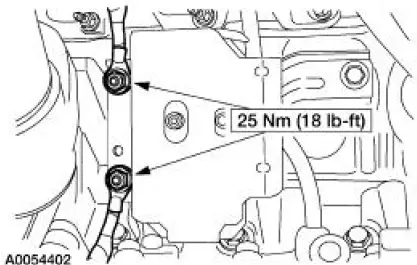
LH mount
1. Position the engine mount and install the bolt and studbolts.
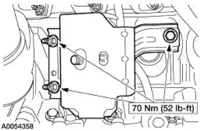
2. Attach the ground cables and install the nuts.
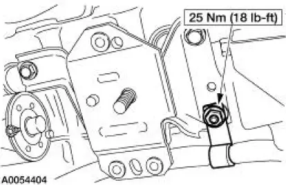
RH mount
3. Position the engine mount and install the bolts and studbolt.
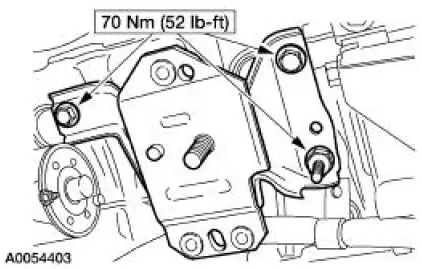
4. Attach the wiring harness and install the nut.
Both mounts
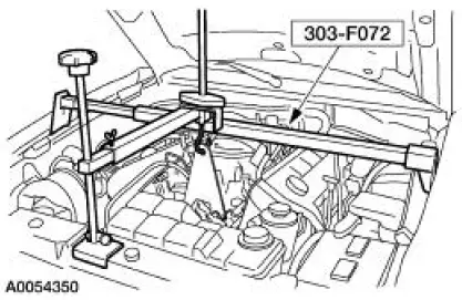
5. Using the jackstands, raise the subframe into position.
6. NOTE: RH shown, LH similar.
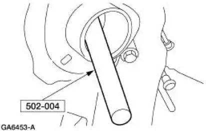
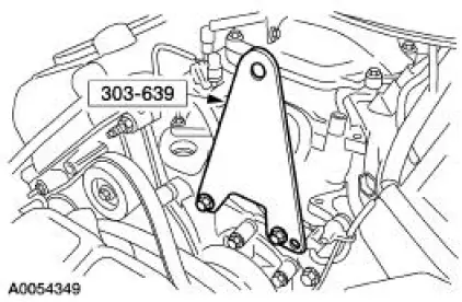
Using the special tool, align the subframe.
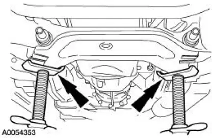
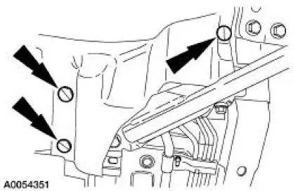
7. NOTE: RH shown, LH similar.
Install the four bolts.
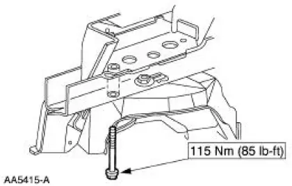
8. NOTE: RH shown, LH similar.
Install the four bolts.
9. Remove the jackstands.
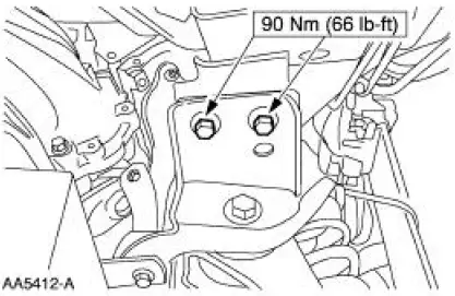
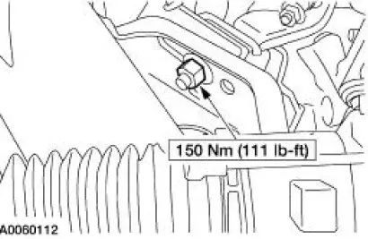
10. NOTE: RH shown, LH similar.
Install the two engine mount nuts.
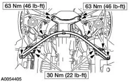
11. Position the cross-brace support and install the 13 bolts.
12. NOTE: RH shown, LH similar Install the six splash-shield pushpins.
13. Install the front springs. For additional information, refer to Section.
14. Remove the special tool.
15. Remove the special tool.
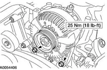
16. Position the generator and install the bolts.
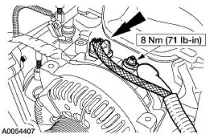
17. Connect the generator electrical connections.
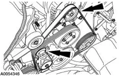
18. Rotate the drive belt tensioner clockwise and attach the drive belt to the generator pulley.
- Make sure the drive belt is routed correctly and is aligned correctly installed on each pulley.
19. Connect the battery ground cable. For additional information, refer to Section.
20. Install the coolant bypass tube. For additional information, refer to Section.
 Removal
Both mounts
1. Disconnect the battery ground cable. For additional information, refer to
Section.
2. Remove the coolant bypass tube. For additional information, refer to Section.
3. Rotate the driv ...
 Engine (Removal)
Special Tool(s)
Lifting Bracket, Engine
303-D087 (D93P-6001-A1)
Lifting Bracket, Engine
303-D088 (D93P-6001-A2)
Spreader Bar
303-D089 (D93P-6001-A3)
Rem ...
Other materials:
Inspection and Verification
1. Verify the customer concern by operating the wiper/washer system.
2. Visually inspect for obvious signs of mechanical and electrical
damage.
Visual Inspection Chart
Mechanical
Electrical
Hoses to windshield washer pump
Wiper l ...
Transmission (REMOVAL)
Special Tool(s)
Retainer, Torque Converter
307-346 (T97T-7902-A)
CAUTION: Whenever a transmission has been disassembled to install new
parts the
transmission fluid cooler tubes must be cleaned and backflushed. Use a suitable
torque
converter/ ...
Refrigerant Identification Testing
Special Tool(s)
Refrigerant Identifier with Air-
Radicator
198-00003 or equivalent
1. NOTE: An A/C refrigerant analyzer must be used to identify gas
samples taken directly from the
refrigeration system or storage containers prior to recoveri ...
