Ford Mustang (1999-2004) Service Manual: Heater Core Backflushing
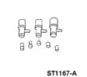
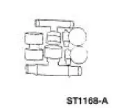
Special Tool(s)
|
|
Flush Kit 164-R3658 or equivalent |
 |
Drain Kit 164-R3662 or equivalent |
Material
| Item | Specification |
| Motorcraft Premium Cooling System Flush VC-1 or equivalent | ESR-M14P7-A |
| Motorcraft Premium Gold Engine Coolant VC-7-A (in Oregon VC-7-B) (yellow color) | WSS-M97B51- A1 |
1. WARNING: Never remove the pressure relief cap while the engine is operating or when the cooling system is hot. Failure to follow these instructions can result in damage to the cooling system or engine or personal injury. To avoid having scalding hot coolant or steam blow out of the degas bottle when removing the pressure relief cap, wait until the engine is cooled, then wrap a thick cloth around the pressure relief cap and turn it slowly. Step back while the pressure is released from the cooling system. When you are sure all the pressure has been released, turn and remove the pressure relief cap (still with a cloth).
Once pressure is released, remove the pressure relief cap.
2. Partially drain the cooling system. For additional information, refer to Cooling System Draining, Filling and Bleeding in this section.
3. NOTE: For additional information, refer to the cooling system flusher manufacturer's operating instructions for particular vehicle hook-up.
Use an appropriate cooling system flusher to backflush the heater core. Use Motorcraft Cooling System Flush VC-1 or equivalent meeting Ford specification ESR-M14P7-A. Flush with water thoroughly after using VC-1 or equivalent prior to refilling the cooling system 4. Fill the cooling system. For additional information, refer to Cooling System Draining, Filling and Bleeding in this section.
 Engine and Radiator Flushing
Special Tool(s)
Coolant System
Drain/Flush/Fill
164-R3673 or equivalent
Flush Kit
164-R3658 or equivalent
Drain Kit
164-R3662 or equivalent
Material
...
 Thermostat - 3.8L
Material
Item
Specification
Gasket Adhesive
TA-6 or equivalent
WSS-M2G408-
A
Motorcraft Premium Gold
Engine Coolant
VC-7-A (in Oregon VC-7-B)
(yellow color)
WSS-M97B51 ...
Other materials:
Connecting Rod - Bushing Diameter
1. Measure the inner diameter of the connecting rod bushing, if equipped.
Verify the diameter is
within specification.
Refer to the appropriate section in Group for the procedure.
If out of specification, install new components as necessary. Refer
...
Inspection and Verification
Certain axle noise or vibration symptoms are also common to the engine,
transmission, wheel
bearings, tires, and other parts of the vehicle. For this reason, be sure that
the cause of the trouble is
in the axle before disassembling, adjusting or repairing th ...
Using voice recognition
This system helps you control many features using voice commands.
This allows you to keep your hands on the wheel and focus on what is in
front of you.
Initiating a Voice Session
Push the voice icon; a tone sounds and Listening appears in the
display. Say an ...

