Ford Mustang (1999-2004) Service Manual: Heating and Defrosting
The heating and defrosting system has the following features:
- Controls the temperature and, during A/C operation, reduces the relative humidity of the air inside the vehicle.
- Delivers heated or cooled air to maintain the vehicle interior temperature and comfort level.
- Controls the A/C blower motor speed.
- Cooling or heating can be adjusted to maintain the desired temperature.
- System uses a reheat method to provide conditioned air to the passenger compartment.
- The blower motor (19805) draws outside air through the air inlet duct from just below the windshield during all system operations except for MAX A/C cooling (when recirculated air is used).
- All airflow from the blower motor passes through the A/C evaporator core (19860).
- The temperature is then regulated by reheating a portion of the air and blending it with the remaining cool air to the desired temperature.
- The temperature blending is varied by the air temperature control door, which regulates the amount of air that flows through and around the heater core (18476), where it is then mixed and distributed.
Heater Core
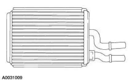
The heater core (18476) consists of fins and tubes arranged to extract heat from the engine coolant and transfer it to air passing through the heater core.
Blower Motor
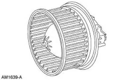
The A/C blower motor (19805 ) pulls air from the air inlet and forces it into the plenum assembly where it is mixed and distributed.
Heater Hoses
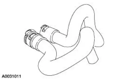
NOTE: The heater water hoses connect to the heater core using quick disconnect couplers. The couplers are an integral part of the hose assemblies and cannot be separately serviced.
The heater water hoses (18472) provide a flexible connection between the engine and cooling system allowing hot water to travel from the engine to the heater core.
 Heating and Ventilation
General Specifications
Torque Specifications
...
 Blower Motor
Removal
1. Disconnect the jumper wire.
2. Disconnect the main harness.
3. Remove the screws.
4. Separate the cover from the motor.
5. Separate the motor from the housing.
6. Disconnect the j ...
Other materials:
Camshaft
Special Tool(s)
Holding Tool, Camshaft
303-446 (T93P-6256-AHR)
Material
Item
Specification
Super Premium SAE 5W-20
Engine Oil
XO-5W20-QSP or equivalent
WSS-M2C153-
H
...
Installation
1. CAUTION: To prevent refrigerant system contamination, do not allow
dirt or other
foreign materials to enter the A/C compressor.
Clean the A/C compressor nose area.
2. Place the shaft seal on the special tool. Lubricate the shaft seal and the
special tool ...
Parking, Rear and License Lamps
Refer to Wiring Diagrams Cell 92 , Exterior for schematic and connector
information.
Special Tool(s)
73 III Automotive Meter or
equivalent
105-R0057
Inspection and Verification
1. Verify the customer concern by operating the parking lamps ...
