Ford Mustang (1999-2004) Service Manual: Ignition Lock Cylinder - Non-Functional
Removal and Installation
1. NOTE: Make sure the front wheels are in the straight-ahead position.
Disconnect the battery ground cable (14301) and wait at least one minute to allow the depletion of the restraint system backup power supply. For additional information, refer to Section.
2. WARNING: To avoid the risk of serious personal injury, read and follow all warnings, cautions, notes and instructions in the deactivation procedure.
Deactivate the supplemental restraint system (SRS). For additional information, refer to Supplemental Restraint System (SRS) Deactivation and Reactivation in this section.
3. WARNING: To reduce the risk of serious personal injury, read and follow all warnings, cautions, notes and instructions in the steering wheel removal and installation procedure.
Remove the steering wheel assembly. For additional information, refer to Wheel in this section.
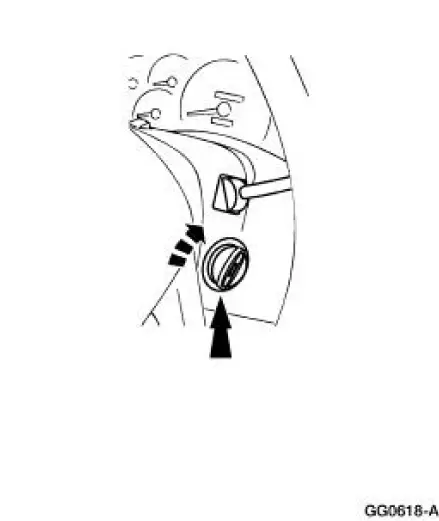
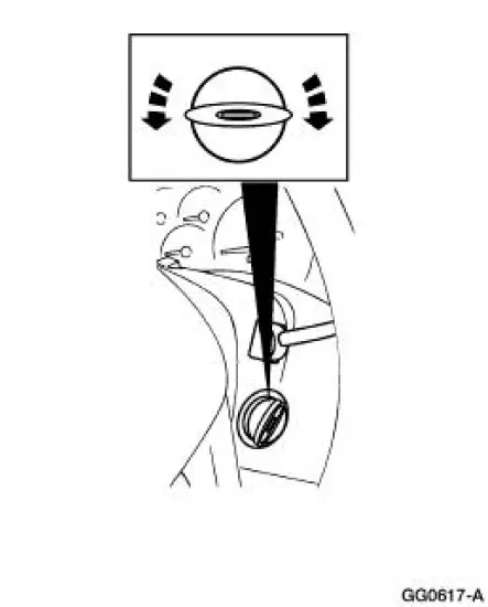
4. Twist off the cap from the ignition switch cylinder.
5. NOTE: The lock cylinder is repaired by discarding the inoperative lock cylinder and building a new lock cylinder using the appropriate lock repair package (F85Z-11582-AA). The lock repair package includes a detailed instruction sheet to build the new lock cylinder to the current key code of the vehicle.
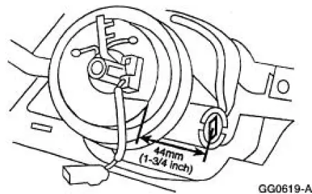
Remove the ignition switch lock cylinder.
- Use a 1/8-inch diameter drill bit to drill out the lock cylinder retaining pin.
- Use a 3/8-inch drill bit to drill down the middle of the ignition lock key slot until the ignition switch lock cylinder breaks loose.
- Remove and discard the ignition switch lock cylinder and clean the drill shavings from the steering column.
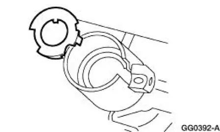
6. Remove the bearing retainer.
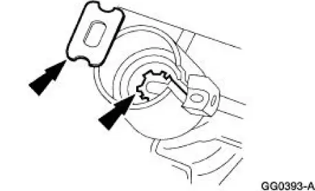
7. Remove the bearing and gear.
- Thoroughly clean all drill shavings from the steering column and inspect it for damage.
8. To install, reverse the removal procedure.
- Install a new ignition switch lock cylinder.
- Verify ignition switch lock cylinder operation.
9. WARNING: To avoid the risk of serious personal injury, read and follow all warnings, cautions, notes and instructions in the reactivation procedure.
Reactivate the supplemental restraint system (SRS). For additional information, refer to Supplemental Restraint System (SRS) Deactivation and Reactivation in this section.
 Ignition Lock Cylinder - Functional
Removal and Installation
1. Disconnect the battery ground cable. For additional information,
refer to Section.
2. Remove the ignition switch lock cylinder (11582).
1. Insert the ignition ...
 Lock Cylinder - Door
Removal
1. NOTE: Individual lock cylinders are repaired by discarding the
inoperative cylinder and building
a new lock cylinder using the appropriate lock repair package. The lock
repair pac ...
Other materials:
Pinpoint Test M: DTC B1891 - Air Bag Tone Warning Indicator Circuit
Shorted to Battery or
Ignition
Normal Operation
The restraints control module (RCM) monitors its connection to the
generic electronic module (GEM) at
pin 10. This connection is used to signal a chime if the air bag
indicator is inoperative and another SRS
fault exists. If the RC ...
System Flushing - CIII Power Steering Pump
WARNING: Do not mix oil types. Any mixture or any unapproved oil can
lead to seal
deterioration and leaks. A leak can ultimately cause loss of fluid, which can
result in a loss of
power steering assist.
1. Remove the fuel pump fuse from the battery junction ...
Bypass Tube - 3.8L
Material
Item
Specification
Motorcraft Premium Gold
Engine Coolant
VC-7-A (in Oregon VC-7-B)
(yellow color)
WSS-M97B51-
A1
Removal and Installation
1. Drain the engine coolant. For additional information, refer to Cooling
System Dra ...
