Ford Mustang (1999-2004) Service Manual: Inspection and Verification
1. Verify the customer concern by operating the system.
2. Visually inspect for obvious signs of mechanical or electrical damage.
Visual Inspection Chart
| Mechanical | Electrical |
|
|
3. If an obvious cause for an observed or reported concern is found, correct the cause (if possible) before proceeding to the next step.
4. If the diagnostic tool does not communicate with the vehicle, refer to the diagnostic tool manual.
5. Carry out the DATA LINK DIAGNOSTIC TEST. If the diagnostic tool responds with:
- CKT 914, CKT 915 or CKT70 - ALL ECUS NO RESP/NOT EQUIP, refer to Section.
- NO RESP/NOT EQUIP for the generic electronic module (GEM), go to Pinpoint Test A.
- NO RESP/NOT EQUIP for the instrument cluster module (ICM), refer to Section.
- System passed, retrieve and record the continuous diagnostic trouble codes (DTCs), erase the continuous DTCs and carry out self-test diagnostics for the GEM or ICM.
6. If the GEM or ICM DTCs retrieved are related to the concern, go to the GEM or ICM Diagnostic Trouble Code (DTC) Index.
7. If no DTCs related to the concern are retrieved, proceed to the Symptom Chart to continue diagnostics.
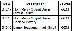
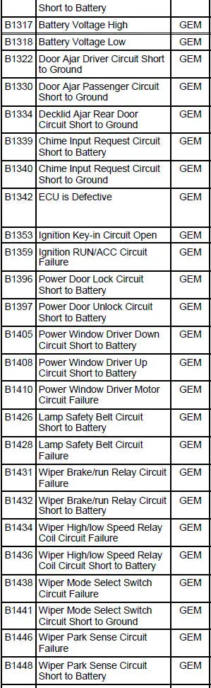
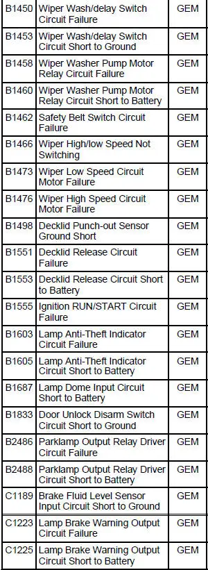
GEM DIAGNOSTIC TROUBLE CODE (DTC) INDEX
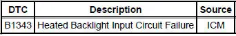
ICM DIAGNOSTIC TROUBLE CODE (DTC) INDEX
Symptom Chart
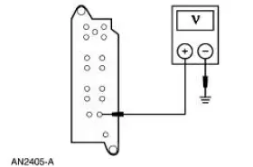
Refer to the Wiring Diagrams for the connector numbers stated in pinpoint tests.
| Condition | Possible Sources | Action |
|
|
|
|
|
|
|
|
|
|
|
|
|
|
|
|
|
|
|
|
|
|
|
|
|
|
|
|
|
|
Pinpoint Tests
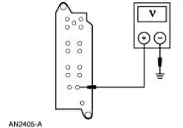
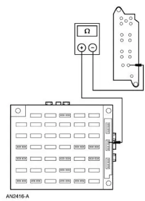
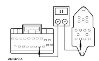
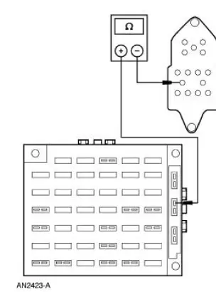
PINPOINT TEST A: NO COMMUNICATION WITH THE GENERIC ELECTRONIC MODULE (GEM)
| Test Step | Result / Action to Take |
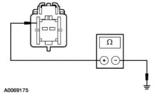
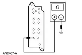
| CAUTION: Use the correct probe adapter(s) when making measurements. Failure to use the correct probe adapter(s) may damage the connector. | |
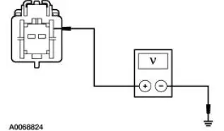
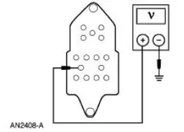
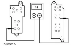
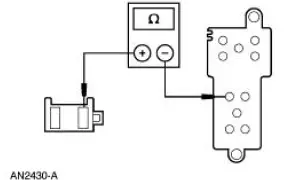
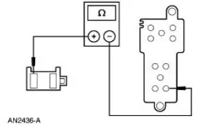
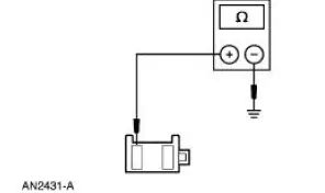
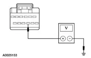
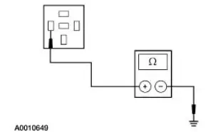
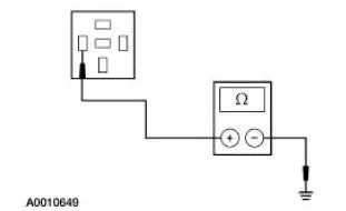
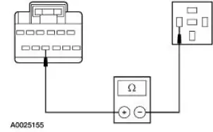
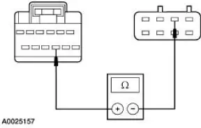
| A1 CHECK THE GENERIC ELECTRONIC MODULE (GEM) POWER SUPPLY | Yes GO to A2 . No REPAIR the circuit(s) in question. TEST the system for normal operation. |
|
|
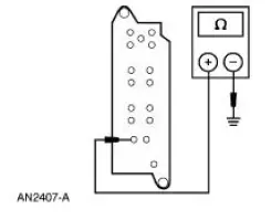
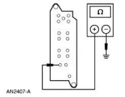
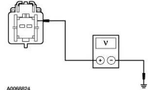
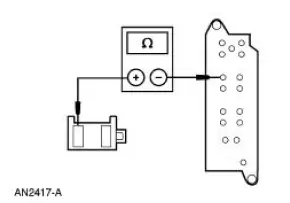
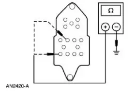
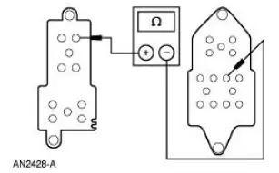
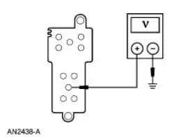
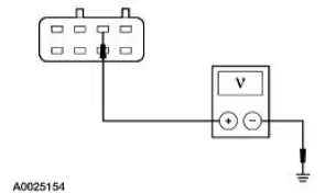
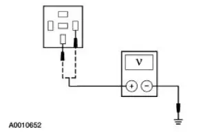
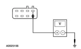
| A2 CHECK THE GEM GROUND CIRCUIT 397 (BK/WH) FOR OPEN | Yes GO to A3 . No REPAIR the circuit(s) in question. TEST the system for normal operation. |
|
|
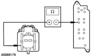
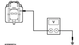
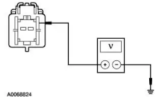
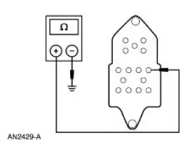
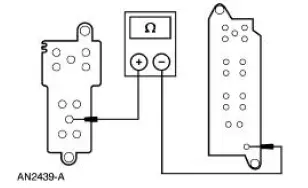
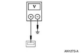
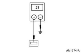
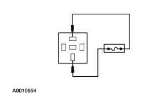
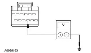
| A3 CHECK CIRCUIT 397 (BK/WH) FOR SHORT TO POWER | Yes REPAIR the circuit. TEST the system for normal operation. No REFER to Section |
|
|
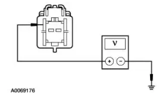
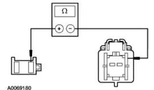
PINPOINT TEST B: ALL POWER WINDOWS ARE INOPERATIVE - CONVERTIBLE
| Test Step | Result / Action to Take |
| B1 CHECK THE POWER SUPPLY TO THE WINDOW REGULATOR CONTROL SWITCH | Yes GO to B2 . No REPAIR the circuit. TEST the system for normal operation |
|
|
| B2 CHECK CIRCUIT 1205 (BK) FOR AN OPEN | Yes INSTALL a new driver window regulator control switch. REFER to Switch-Window Regulator Control in this section. TEST the system for normal operation. No REPAIR the circuit. TEST the system for normal operation. |
|
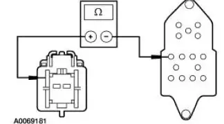
PINPOINT TEST C: ALL POWER WINDOWS ARE INOPERATIVE - COUPE
| Test Step | Result / Action to Take |
| C1 CHECK THE POWER SUPPLY TO THE WINDOW REGULATOR CONTROL SWITCH | Yes GO to C2 . No REPAIR the circuit. TEST the system for normal operation |
|
|
| C2 CHECK CIRCUIT 1205 (BK) FOR AN OPEN | Yes INSTALL a new driver window regulator control switch. REFER to Switch-Window Regulator Control in this section. TEST the system for normal operation. No REPAIR the circuit. TEST the system for normal operation. |
|

PINPOINT TEST D: A SINGLE POWER WINDOW IS INOPERATIVE - DRIVER, CONVERTIBLE
| Test Step | Result / Action to Take |
| D1 CHECK THE IGNITION SWITCH INPUT TO THE GEM | Yes GO to D2 . No REFER to Section for ignition switch diagnosis. |
|
|
| D2 CHECK THE DRIVER WINDOW REGULATOR CONTROL SWITCH INPUT TO THE GEM | Yes GO to D9 . No GO to D3 . |
|
|
| D3 CHECK THE POWER SUPPLY TO THE WINDOW REGULATOR CONTROL SWITCH | Yes GO to D4 . No GO to D8 . |
|
|
| D4 CHECK CIRCUIT 1205 (BK) FOR AN OPEN | Yes GO to D5 . No REPAIR the circuit. TEST the system for normal operation. |
|
|
| D5 CHECK THE DRIVER WINDOW REGULATOR CONTROL SWITCH | Yes GO to D6 . No INSTALL a new driver window regulator control switch. REFER to Switch-Window Regulator Control in this section. TEST the system for normal operation. |
|
|
| D6 CHECK CIRCUIT 226 (WH/BK) FOR A SHORT TO BATTERY | Yes REPAIR the circuit. TEST the system for normal operation. No GO to D7 . |
|
|
| D7 CHECK CIRCUIT 991 (TN/LB) AND 992 (WH/BK) FOR AN OPEN | Yes INSTALL a new GEM. REFER to Section. TEST the system for normal operation. No REPAIR the circuit. TEST the system for normal operation. |
|
|
| D8 CHECK CIRCUIT 400 (LB/BK) FOR AN OPEN | Yes REPAIR the power supply to CJB circuit breaker 43 (20A). TEST the system for normal operation. No REPAIR the circuit. TEST the system for normal operation. |
|
|
| D9 CHECK THE GEM CONTROL OF THE DRIVER POWER WINDOW | Yes INSTALL a new GEM. REFER to Section. TEST the system for normal operation. No GO to D10 |
|
|
| D10 CHECK THE WINDOW REGULATOR MOTOR OPERATION | Yes GO to D11 . No INSTALL a new window regulator motor. REFER to Motor-Window Regulator in this section. TEST the system for normal operation. |
|
|
| D11 CHECK CIRCUIT 992 (WH/BK) FOR AN OPEN BETWEEN THE DRIVER WINDOW MOTOR AND THE WINDOW REGULATOR CONTROL SWITCH | Yes GO to D12 . No REPAIR the circuit. TEST the system for normal operation. |
|
|
| D12 CHECK CIRCUIT 226 (WH/BK) FOR AN OPEN | Yes GO to D13 . No REPAIR the circuit. TEST the system for normal operation. |
|
|
| D13 CHECK CIRCUIT 400 (LB/BK) FOR AN OPEN TO THE GEM | Yes INSTALL a new GEM. REFER to Section. TEST the system for normal operation. No REPAIR the circuit. TEST the system for normal operation |
|
PINPOINT TEST E: A SINGLE POWER WINDOW IS INOPERATIVE - DRIVER, COUPE
| Test Step | Result / Action to Take |
| E1 CHECK THE IGNITION SWITCH INPUT TO THE GEM | Yes GO to E2 . No REFER to Section for ignition switch diagnosis. |
|
|
| E2 CHECK THE DRIVER WINDOW REGULATOR CONTROL SWITCH INPUT TO THE GEM | Yes GO to E9 . No GO to E3 . |
|
|
| E3 CHECK THE POWER SUPPLY TO THE WINDOW REGULATOR CONTROL SWITCH | Yes GO to E4 . No GO to E8 . |
|
|
| E4 CHECK CIRCUIT 1205 (BK) FOR AN OPEN | Yes GO to E5 . No REPAIR the circuit. TEST the system for normal operation. |
|
|
| E5 CHECK THE DRIVER WINDOW REGULATOR CONTROL SWITCH | Yes GO to E6 . No INSTALL a new driver window regulator control switch. REFER to Switch-Window Regulator Control in this section. TEST the system for normal operation. |
|
|
| E6 CHECK CIRCUIT 226 (WH/BK) FOR A SHORT TO BATTERY | Yes REPAIR the circuit. TEST the system for normal operation. No GO to E7 . |
|
|
| E7 CHECK CIRCUIT 991 (TN/LB) AND 992 (WH/BK) FOR AN OPEN | Yes INSTALL a new GEM. REFER to Section. TEST the system for normal operation. No REPAIR the circuit. TEST the system for normal operation. |
|
|
| E8 CHECK CIRCUIT 400 (LB/BK) FOR AN OPEN | Yes REPAIR the power supply to CJB circuit breaker 43 (20A). TEST the system for normal operation. No REPAIR the circuit. TEST the system for normal operation. |
|
|
| E9 CHECK THE GEM CONTROL OF THE DRIVER POWER WINDOW | Yes INSTALL a new GEM. REFER to Section. TEST the system for normal operation. No GO to E10 . |
|
|
| E10 CHECK THE WINDOW REGULATOR MOTOR OPERATION | Yes GO to E11 . No INSTALL a new window regulator motor. REFER to Motor-Window Regulator in this section. TEST the system for normal operation. |
|
|
| E11 CHECK CIRCUIT 992 (WH/BK) FOR AN OPEN BETWEEN THE DRIVER WINDOW MOTOR AND THE WINDOW REGULATOR CONTROL SWITCH | Yes GO to E12 . No REPAIR the circuit. TEST the system for normal operation. |
|
|
| E12 CHECK CIRCUIT 226 (WH/BK) FOR AN OPEN | Yes GO to E13 . No REPAIR the circuit. TEST the system for normal operation. |
|
|
| E13 CHECK CIRCUIT 400 (LB/BK) FOR AN OPEN TO THE GEM | Yes INSTALL a new GEM. REFER to Section. TEST the system for normal operation. No REPAIR the circuit. TEST the system for normal operation. |
|
PINPOINT TEST F: A SINGLE POWER WINDOW IS INOPERATIVE - PASSENGER FRONT
| Test Step | Result / Action to Take |
| F1 CHECK THE OPERATION FROM THE DRIVER WINDOW REGULATOR CONTROL SWITCH | Yes GO to F2 . No GO to F15 . |
|
|
| F2 CHECK CIRCUIT 334 (RD/YE) FOR GROUND | Yes GO to F8 . No GO to F3 . |
|
|
| F3 CHECK CIRCUIT 314 (TN/LB) FOR GROUND | Yes GO to F7 . No GO to F4 for convertible or GO to F5 for coupe. |
|
|
| F4 CHECK CIRCUIT 314 (TN/LB) FOR AN OPEN (CONVERTIBLE) | Yes INSTALL a new driver window regulator control switch. REFER to Switch-Window Regulator Control in this section. TEST the system for normal operation. No REPAIR the circuit. TEST the system for normal operation. |
|
|
| F5 CHECK CIRCUIT 314 (TN/LB) FOR AN OPEN (COUPE) | Yes GO to F6 . No REPAIR the circuit. TEST the system for normal operation. |
|
|
| F6 CHECK PASSENGER UP GROUND CIRCUIT 1205 (BK) FOR AN OPEN | Yes INSTALL a new driver window regulator control switch. REFER to Switch-Window Regulator Control in this section. TEST the system for normal operation. No REPAIR the circuit. TEST the system for normal operation. |
|
|
| F7 CHECK CIRCUIT 334 (RD/YE) FOR AN OPEN | Yes INSTALL a new passenger window regulator control switch. TEST the system for normal operation. No REPAIR the circuit. TEST the system for normal operation. |
|
|
| F8 CHECK CIRCUIT 333 (YE/RD) FOR GROUND | Yes GO to F14 . No GO to F9 . |
|
|
| F9 CHECK CIRCUIT 313 (WH/YE) FOR GROUND | Yes GO to F13 . No GO to F10 for convertible or GO to F11 for coupe. |
|
|
| F10 CHECK CIRCUIT 313 (WH/YE) FOR AN OPEN (CONVERTIBLE) | Yes INSTALL a new driver window regulator control switch. REFER to Switch-Window Regulator Control in this section. TEST the system for normal operation. No REPAIR the circuit. TEST the system for normal operation. |
|
|
| F11 CHECK CIRCUIT 313 (WH/YE) FOR AN OPEN (COUPE) | Yes GO to F12 . No REPAIR the circuit. TEST the system for normal operation. |
|
|
| F12 CHECK PASSENGER DOWN GROUND CIRCUIT 1205 (BK) FOR AN OPEN | Yes INSTALL a new driver window regulator control switch. REFER to Switch-Window Regulator Control in this section. TEST the system for normal operation. No REPAIR the circuit. TEST the system for normal operation. |
|
|
| F13 CHECK CIRCUIT 333 (YE/RD) FOR AN OPEN | Yes INSTALL a new passenger window regulator control switch. TEST the system for normal operation. No REPAIR the circuit. TEST the system for normal operation. |
|
|
| F14 CHECK THE DRIVER WINDOW REGULATOR CONTROL SWITCH | Yes INSTALL a new passenger window regulator motor. REFER to Motor-Window Regulator in this section. TEST the system for normal operation. No INSTALL a new driver window regulator control switch. REFER to Switch-Window Regulator Control in this section. TEST the system for normal operation. |
|
|
| F15 CHECK THE POWER SUPPLY TO THE PASSENGER WINDOW REGULATOR CONTROL SWITCH | Yes INSTALL a new passenger window regulator control switch. TEST the system for normal operation. No For convertible, GO to F16 . For coupe, REPAIR the circuit. TEST the system for normal operation. |
|
|
| F16 CHECK CIRCUIT 194 (PK) FOR AN OPEN | Yes INSTALL a new driver window regulator control switch. REFER to Switch-Window Regulator Control in this section. TEST the system for normal operation. No REPAIR the circuit. TEST the system for normal operation. |
|

PINPOINT TEST G: A SINGLE POWER WINDOW IS INOPERATIVE - REAR, CONVERTIBLE ONLY
| Test Step | Result / Action to Take |
| G1 CHECK CIRCUIT 316 (YE/LB) OR 319 (YE/BK) FOR GROUND | Yes GO to G3 . No GO to G2 . |
|
|
| G2 CHECK CIRCUIT 316 (YE/LB) OR 319 (YE/BK) FOR AN OPEN | Yes INSTALL a new driver window regulator control switch. REFER to Switch-Window Regulator Control in this section. TEST the system for normal operation. No REPAIR the circuit. TEST the system for normal operation. |
|
|
| G3 CHECK CIRCUIT 317 (GY/OG) OR 320 (RD/BK) FOR GROUND | Yes GO to G5 . No GO to G4 . |
|
|
| G4 CHECK CIRCUIT 317 (GY/OG) OR 320 (RD/BK) FOR AN OPEN | Yes INSTALL a new driver window regulator control switch. REFER to Switch-Window Regulator Control in this section. TEST the system for normal operation. No REPAIR the circuit. TEST the system for normal operation. |
|
|
| G5 CHECK DRIVER WINDOW REGULATOR CONTROL SWITCH | Yes INSTALL a new rear window regulator motor. REFER to Motor- Window Regulator, Quarter in this section. TEST the system for normal operation. No INSTALL a new driver window regulator control switch. REFER to Switch-Window Regulator Control in this section. TEST the system for normal operation. |
|
PINPOINT TEST H: THE DEFROST SYSTEM IS INOPERATIVE
| Test Step | Result / Action to Take |
| H1 CHECK POWER TO INDICATOR LIGHT | Yes GO to H2 . No GO to H3 . |
|
|
| H2 CHECK CIRCUIT 186 (BR/LB) FOR AN OPEN | Yes GO to H7 . No REPAIR the circuit. TEST the system for normal operation. |
|
|
| H3 CHECK THE DIAGNOSTIC TROUBLE CODES (DTCS) | Yes GO to H4 . No GO to H6 . |
|
|
| H4 CHECK CIRCUIT 175 (BK/YE) | Yes GO to H5 . No GO to H16 . |
|
|
| H5 CHECK CIRCUIT 175 (BK/YE) FOR A SHORT TO POWER | Yes REPAIR the circuit. CLEAR the DTCs. REPEAT the self-test. No INSTALL a new rear window defrost switch. REFER to Rear Window Defrost Switch in this section. TEST the system for normal operation. |
|
|
| H6 CHECK THE REAR HEATED WINDOW GRID POWER | Yes GO to H7 . No GO to H8 . |
|
|
| H7 CHECK THE REAR WINDOW GROUND | Yes CARRY OUT the heated rear window grid wire test. REFER to Grid Wire Test in Component Tests in this section. TEST the system for normal operation. No REPAIR the circuit. TEST the system for normal operation. |
|
|
| H8 CHECK CIRCUIT 727 (YE/BK) | Yes GO to H9 . No GO to H11 . |
|
|
| H9 CHECK CIRCUIT 185 (BK) FOR POWER | Yes GO to H10 . No REPAIR the supply circuit. TEST the system for normal operation. |
|
|
| H10 CHECK CIRCUIT 186 (BR/LB) FOR AN OPEN | Yes INSTALL a new heated rear window relay. TEST the system for normal operation. No REPAIR circuit 186 (BR/LB). TEST the system for normal operation. |
|
|
| H11 CHECK ICM OUTPUT | Yes GO to H13 . No GO to H12 . |
|
|
| H12 CHECK CIRCUIT 727 (YE/BK) FOR AN OPEN | Yes GO to H16 . No REPAIR the circuit. TEST the system for normal operation. |
|
|
| H13 CHECK POWER TO REAR WINDOW DEFROST SWITCH | Yes GO to H14 . No REPAIR the supply circuit. TEST the system for normal operation. |
|
|
| H14 CHECK INPUT TO THE ICM | Yes GO to H16 . No GO to H15 . |
|
|
| H15 CHECK CIRCUIT 175 (BK/YE) FOR AN OPEN | Yes INSTALL a new rear window defrost switch. REFER to Rear Window Defrost Switch in this section. TEST the system for normal operation. No REPAIR the circuit. TEST the system for normal operation. |
|
|
| H16 CHECK THE ICM FOR CORRECT OPERATION | Yes INSTALL a new ICM. REFER to Section. CLEAR the DTCs. REPEAT the self-test. No The system is operating correctly at this time. Concern may have been caused by a loose or corroded connector. CLEAR the DTCs. REPEAT the self-test. |
|
PINPOINT TEST I: THE DEFROST SYSTEM WILL NOT SHUT OFF AUTOMATICALLY
| Test Step | Result / Action to Take |
| I1 CHECK CIRCUIT 727 (YE/BK) | Yes GO to I3 . No GO to I2 . |
|
|
| I2 CHECK CIRCUIT 727 (YE/BK) FOR A SHORT TO GROUND | Yes GO to I4 . No REPAIR the circuit. TEST the system for normal operation. |
|
|
| I3 CHECK CIRCUIT 186 (BN/LB) FOR A SHORT TO POWER | Yes REPAIR the circuit. TEST the system for normal operation. No INSTALL a new heated rear window relay. TEST the system for normal operation. |
|
|
| I4 CHECK THE ICM FOR CORRECT OPERATION | Yes INSTALL a new ICM. REFER to Section. CLEAR the DTCs. REPEAT the self-test. No The system is operating correctly at this time. Concern may have been caused by a loose or corroded connector. CLEAR the DTCs. REPEAT the self-test. |
|
 Principles of Operation
Power Window Control
NOTE: Battery power and ground must be removed before disconnecting the
GEM connectors to
avoid setting false DTCs.
The driver power window one-touch down operation is contr ...
 Component Tests
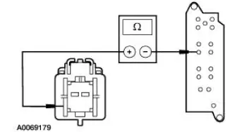
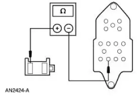
Grid Wire Test
1. Using a bright lamp inside the vehicle, inspect the wire grid from
the exterior. A broken grid wire
will appear as a brown spot.
2. Run the engine at idle. Set the rear win ...
Other materials:
Fuel Charging And Controls
The fuel injection supply manifold (9F792):
delivers fuel to the fuel injector.
receives fuel from the fuel supply line.
The throttle body (9E926):
controls air supply to the upper intake manifold (9424) by positioning
the throttle plate.
connects the ...
Instrument Cluster (Description and Operation)
The instrument cluster (10849) consists of the following components:
Instrument Cluster-Base 3.8L Engine
Instrument Cluster-Base 4.6L Engine
Instrument Cluster-Cobra
...
Key Release Button
Removal
1. Disconnect the battery ground cable.
2. Remove the ignition switch lock cylinder.
1. Insert the ignition key into the ignition switch lock cylinder and
turn to RUN position.
2. Push the ignition switch lock cylinder release tab with a p ...
