Ford Mustang (1999-2004) Service Manual: Installation
WARNING: To reduce the risk of serious personal injury, read and follow all warnings, cautions and notes at the beginning of the removal procedure.
1. Disconnect the battery ground cable and wait at least one minute. For additional information, refer to Section.
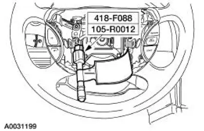
2. Remove the restraint system diagnostic tool from the clockspring electrical connector at the top of the steering column.
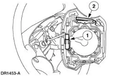
3. Connect the driver air bag module.
1. Connect the driver air bag module electrical connector.
2. Position the driver air bag module to the steering wheel.
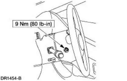
4. Install the two driver air bag module bolts.
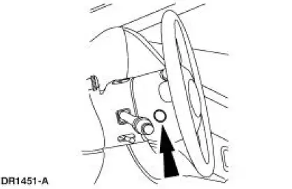
5. Install the two steering wheel back cover plugs.
6. Connect the battery ground cable. For additional information, refer to Section .
7. With the restraint system diagnostic tools still installed at the remaining deployable devices, prove out the supplemental restraint system (SRS). For additional information, refer to Air Bag Supplemental Restraint System (SRS) in the Diagnosis and Testing portion of this section.
8. WARNING: To avoid accidental deployment and possible personal injury, the backup power supply must be depleted before repairing or replacing any front or side air bag supplemental restraint system (SRS) components and before servicing, replacing, adjusting or striking components near the front or side air bag sensors, such as doors, instrument panel, console, door latches, strikers, seats and hood latches.
Please refer to the appropriate vehicle shop manual to determine location of the front air bag sensors.
The side air bag sensors are located at or near the base of the B-pillar.
To deplete the backup power supply energy, disconnect the battery ground cable and wait at least one minute. Be sure to disconnect auxiliary batteries and power supplies (if equipped).
Disconnect the battery ground cable and wait at least one minute. For additional information, refer to Section.
9. Restore the vehicle to operating condition.
1. WARNING: To reduce the risk of serious personal injury, read and follow all warnings, cautions, notes, and instructions in the supplemental restraint system (SRS) deactivation/reactivation procedure.
Reactivate the supplemental restraint system (SRS). For additional information, refer to Supplemental Restraint System (SRS) Deactivation and Reactivation in the General Procedures portion of this section.
2. WARNING: The restraint system diagnostic tool is for restraint system service only. Remove from the vehicle prior to road use. Failure to remove could result in injury and possible violation of vehicle safety standards.
With all the restraint system diagnostic tools removed, prove out the supplemental restraint system (SRS). For additional information, refer to Air Bag Supplemental Restraint System (SRS) in the Diagnosis and Testing portion of this section.
 Removal
WARNING: Always wear safety glasses when repairing an air bag
supplemental restraint
system (SRS) vehicle and when handling an air bag module. This will
reduce the risk of injury
in the even ...
 Passenger Air Bag Module
Special Tool(s)
Diagnostic Tool, Restraint
System (2 Req'd)
418-F088 (105-R0012)
...
Other materials:
Output Shaft
Special Tool(s)
Remover, Drive Pinion Bearing
Cone
205-D002 (D79L-4621-A) or
equivalent
Installer, Drive Pinion Bearing
Cone
205-011 (T57L-4621-B)
...
Planetary Gear Support Assembly and Planetary One-Way
Clutch
Disassembly and Assembly
1. NOTE: Inspect the outer and inner races for scores or damaged
surface areas where rollers
contact the races. Inspect the rollers and springs for excessive wear or damage.
Inspect the
spring and cage for bent or damaged ...
Mass Air Flow (MAF) Sensor - 3.8L
Removal
CAUTION: The mass air flow (MAF) sensor hot wire sensing
element and housing are
calibrated as a unit and must be repaired as a complete assembly. Do not
damage the sensing
element (internal to housing) or possible failure to the mass air f ...
