Ford Mustang (1999-2004) Service Manual: Wheel Hub or Axle Flange Face Runout
NOTE: If the axle shaft assembly is removed, check runout of the shaft itself. The forged (unmachined) part of the shaft is allowed to have as much as 3.0 mm (0.120 inch) runout. This alone will not cause a vibration condition.
1. Position the special tool on the wheel hub or axle flange face, as close to the outer edge as possible. Zero the indicator to allow the pointer to deflect either way.
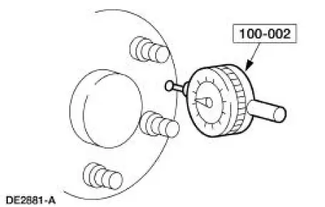
2. Rotate the hub or flange one full turn and note the maximum and minimum readings. The difference between the maximum and minimum readings will be the total face runout. The runout must not exceed 0.127 mm (0.005 inch).
Drive Pinion Stem and Pinion Flange
Check the pinion flange runout when all other checks have failed to show the cause of vibration.
One cause of excessive pinion flange runout is incorrect installation of the axle drive pinion seal.
Check to see if the spring on the seal lip has been dislodged before installing the ring gear and pinion.
Axle Noise
NOTE: Before disassembling the axle to diagnose and correct gear noise, eliminate the tires, exhaust, trim items, roof racks, axle shafts and wheel bearings as possible causes. The noises described as follows usually have specific causes that can be diagnosed by observation as the unit is disassembled. The initial clues are the type of noise heard during the road test.
 Wheel Hub or Axle Flange Bolt Circle Runout
NOTE: The brake discs must be removed to carry out all runout
measurements.
1. Position the special tool perpendicular to the wheel hub or axle flange bolt,
as close to the hub
or flange face as po ...
 Gear Howl and Whine
Howling or whining of the ring gear and pinion is due to an incorrect gear
pattern, gear damage or
incorrect bearing preload. ...
Other materials:
Manual transmission
Using the Clutch
Manual transmission vehicles have a starter interlock that prevents
starting the engine unless the clutch pedal is fully pressed.
To start the vehicle:
1. Make sure the parking brake is fully set.
2. Press the clutch pedal to the
floor, then ...
Removal
1. Remove the differential assembly from the differential housing. For
additional information, refer
to Differential Case in this section.
2. CAUTION: Record the torque necessary to maintain rotation of the drive
pinion gear
through several revolutions prio ...
Inspection and Verification
CAUTION: Do not hold the steering wheel (3600) at the stops for an
extended amount of
time. Damage to the power steering pump (3A674) will result.
NOTE: Make the following preliminary checks before repairing the
steering system:
1. Verify the customer conce ...
