Ford Mustang (1999-2004) Service Manual: Installation
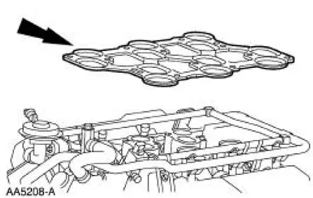
1. Install a new upper intake manifold gasket.
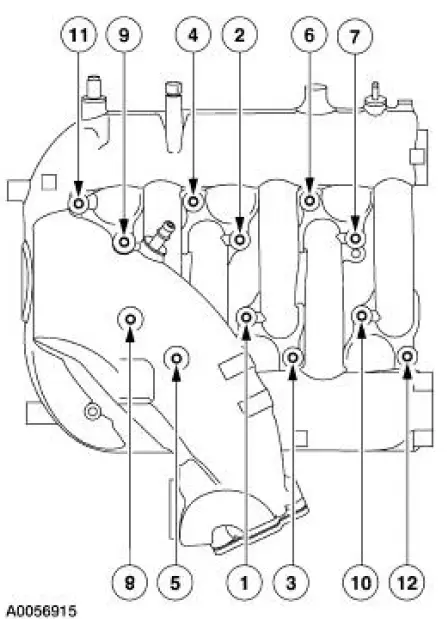
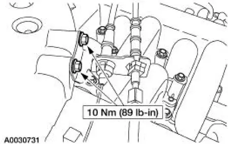
2. NOTE: Refer to the location note made during removal and make sure the bolts are installed in the correct locations.
Install the upper intake manifold. Tighten the bolts in two stages in the sequence shown.
- Stage 1: Tighten to 10 Nm (89 lb-in).
- Stage 2: Rotate an additional 90 degrees (1/4 turn).
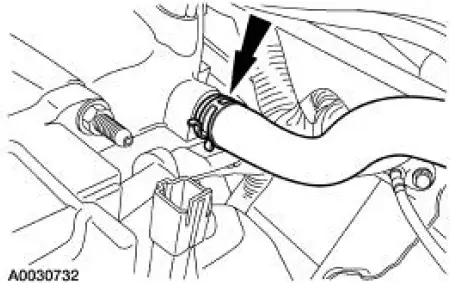
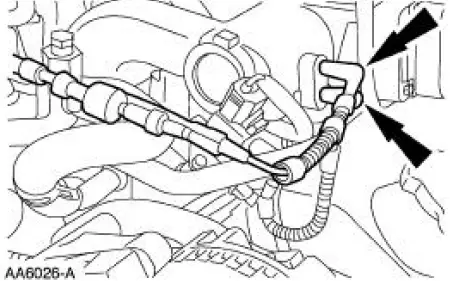
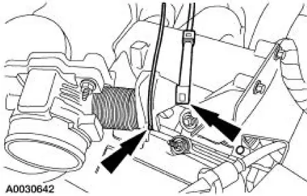
3. Connect the vacuum hose.
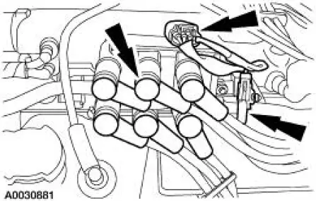
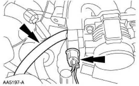
4. Connect the following:
- Ignition coil electrical connector.
- Radio interference capacitor electrical connector.
- Spark plug wires.
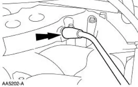
5. Connect the vacuum hoses.
6. Connect the PCV tube.
7. Connect the differential pressure feedback EGR system electrical and vacuum connections.
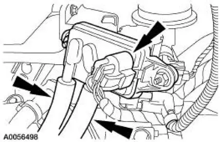
8. Connect the EGR vacuum regulator solenoid electrical and vacuum connections.
9. Position the accelerator cable bracket and install the bolts.
10. Connect the accelerator and speed control cables to the throttle body cam.
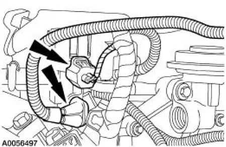
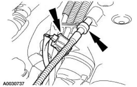
11. Connect the EVAP return tube and the TP sensor electrical connector.
12. Connect the vacuum hose and the IAC valve electrical connector.
13. Install the engine air cleaner outlet pipe. For additional information, refer to Section .
14. Connect the battery ground cable. For additional information, refer to Section .
 Removal
1. Disconnect the battery ground cable. For additional information, refer
to Section.
2. Remove the engine air cleaner outlet pipe. For additional information,
refer to Section.
3. Disconnect ...
 Lower Intake Manifold
Material
...
Other materials:
Master Cylinder - Hydro-Boost
Removal
1. Disconnect the fluid level sensor connector.
2. Disconnect the brake tubes.
3. Remove the brake master cylinder nuts.
4. Remove the brake master cylinder (2140).
Installation
1. To install, reverse the removal procedure.
Bleed the brak ...
Cabin air filter
Note: Make sure you have a cabin air filter installed at all times.
This
prevents foreign objects from entering the system. Running the system
without a filter in place could result in degradation or damage to the
system.
Your vehicle is equipped with a cabi ...
Component Tests
Drive Belt Noise/Flutter
Drive belt chirp occurs due to pulley misalignment or excessive pulley runout.
It can be the result of a
damaged pulley or an incorrectly aligned pulley.
To correct, determine the area where the noise comes from. Check each of the
p ...
