Ford Mustang (1999-2004) Service Manual: Removal
1. Disconnect the battery ground cable. For additional information, refer to Section.
2. Remove the engine air cleaner outlet pipe. For additional information, refer to Section.
3. Disconnect the vacuum hose and the idle air control (IAC) valve electrical connector.
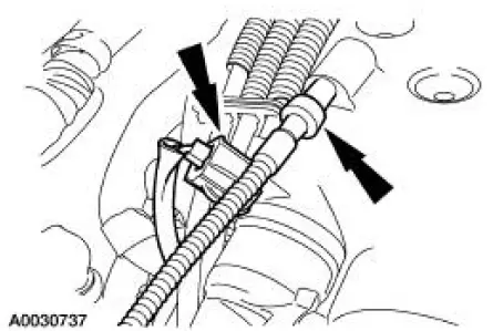
4. Disconnect the throttle position (TP) sensor electrical connector and the evaporative emissions (EVAP) return tube.
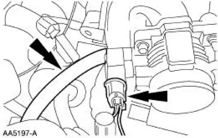
5. Disconnect the accelerator and the speed control cables from the throttle body cam.
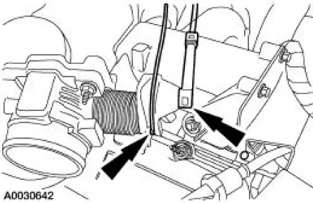
6. Remove the bolts and position the accelerator cable bracket assembly aside.
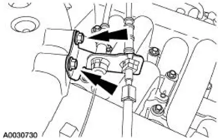
7. Disconnect the differential pressure feedback exhaust gas recirculation (EGR) system electrical and vacuum connections.
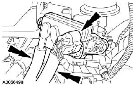
8. Disconnect the EGR vacuum regulator solenoid electrical and vacuum connections.
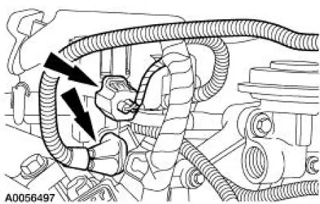
9. Disconnect the positive crankcase ventilation (PCV) tube.
10. Disconnect the vacuum hoses.
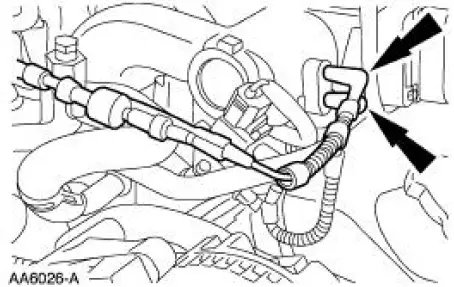
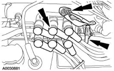
11. Disconnect the following:
- Ignition coil electrical connector.
- Radio interference capacitor electrical connector.
- Spark plug wires.
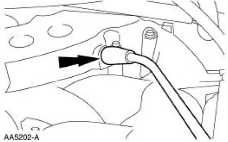
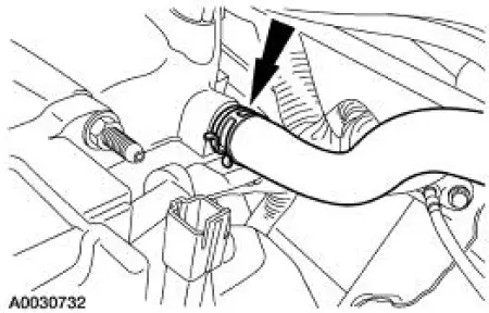
12. Disconnect the vacuum hose.
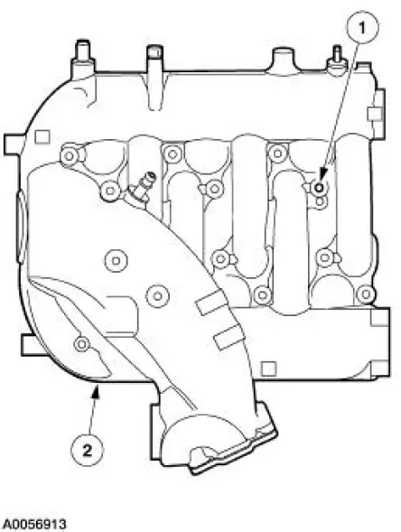
13. NOTE: For ease in installation, record the location of the long bolts and the short bolts.
Remove the upper intake manifold.
1. Remove the 12 bolts.
2. Remove the upper intake manifold.
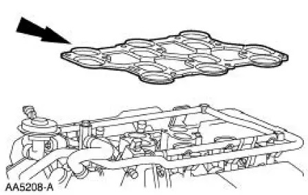
14. Remove and discard the upper intake manifold gasket.

 Installation
1. Install a new upper intake manifold gasket.
2. NOTE: Refer to the location note made during removal and make sure
the bolts are installed in
the correct locations.
Install the upper intake mani ...
Other materials:
SecuriLock® passive anti-theft system
Note: The system is not compatible with non-Ford aftermarket remote
start systems. Use of these systems may result in vehicle starting
problems and a loss of security protection.
Note: Metallic objects, electronic devices or a second coded key on the
same key ...
Economical driving
Fuel economy is affected by several things, such as how you drive, the
conditions you drive under and how you maintain your vehicle.
There are some things to keep in mind that may improve your fuel
economy:
• Accelerate and slow down in a smooth, moderate f ...
Removal
NOTE: This procedure applies to both the LH and RH halfshafts.
1. CAUTION: The vehicle must be on level ground and at curb height.
Mark the rear shock absorber relative to the protective sleeve.
During installation, raise the suspension to this reference ...
