Ford Mustang (1999-2004) Service Manual: Installation
1. CAUTION: In order to prevent foreign material from contaminating the engine block or the engine front cover it is necessary to seal the coolant and oil passages of both components. Failure to follow these directions will result in engine damage.
CAUTION: Do not use a surface conditioning pad or any other type of fibrous abrasive disc to clean the gasket surfaces. Failure to follow these directions will result in engine damage.
Clean and inspect the engine block and front cover as follows:
- Pack the exposed portion of the oil pan with clean shop towels.
- Plug the oil and coolant passages.
- Clean the gasket surfaces.
- Clean all surfaces requiring gasket sealant with metal surface cleaner.
- Using compressed air, remove any remaining foreign material from the engine block and engine front cover.
- Remove the shop towels from the oil pan.
- Remove the plugs or seals from the engine block and engine front cover.
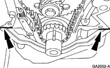
2. NOTE: If the engine front cover is not secured within four minutes, the sealant must be removed and the sealing area cleaned with metal surface cleaner. Allow to dry until there is no sign of wetness, or four minutes, whichever is longer. Failure to follow this procedure can cause future oil leakage.
Apply a small amount of silicone gasket and sealant as shown.
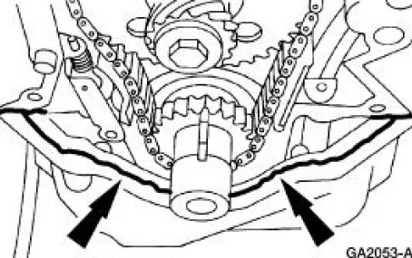
3. NOTE: If the engine front cover is not secured within four minutes, the sealant must be removed and the sealing area cleaned with metal surface cleaner. Allow to dry until there is no sign of wetness, or four minutes, whichever is longer. Failure to follow this procedure can cause future oil leakage.
Install the engine front cover gasket and apply silicone gasket and sealant as shown.
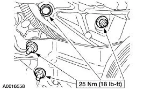
4. Install the engine front cover and bolts.
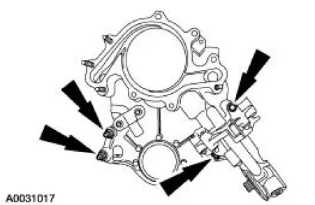
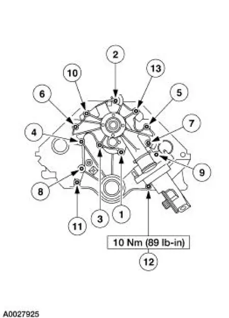
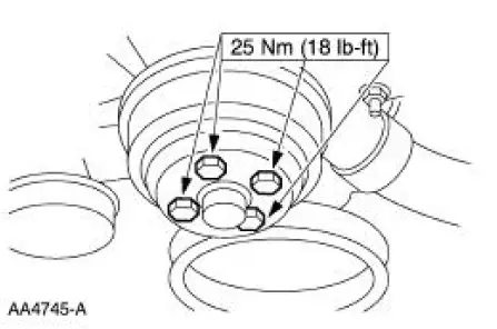
5. Install the water pump. Install the nuts and bolts.
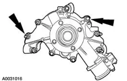
6. NOTE: The number 12 bolt is not part of the tightening sequence.
Tighten the fasteners to 26 Nm (19 lb-ft) in the sequence shown.
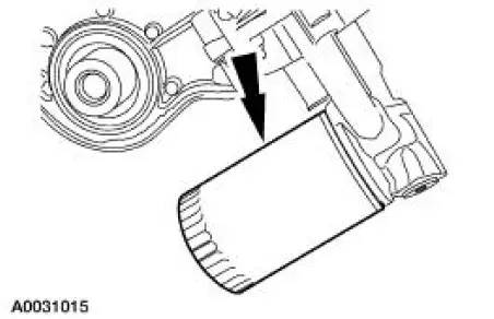
7. Install a new oil filter.
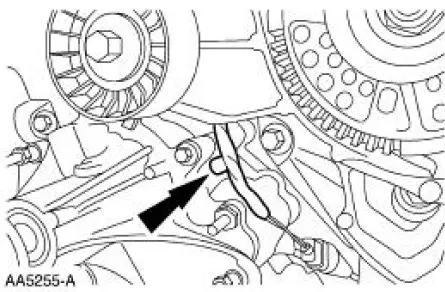
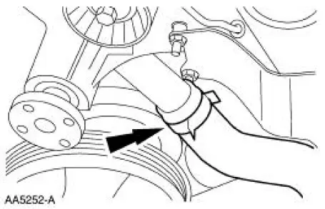
8. Install the wiring harness pin-type retainer.
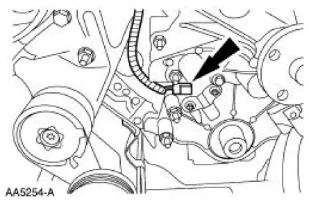
9. Connect the crankshaft position sensor electrical connector.
10. Connect the lower radiator hose.
11. Install the camshaft synchronizer assembly. For additional information, refer to Section.
12. Install the heater water outlet tube. For additional information, refer to Section.
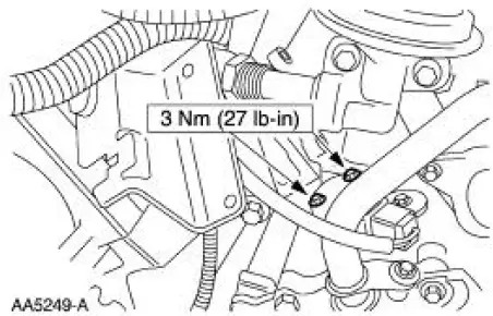
13. Install the camshaft position (CMP) sensor, and connect the electrical connector.
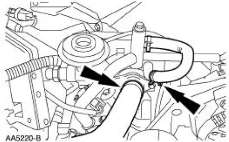
14. Connect the bypass hose and the upper radiator hose.
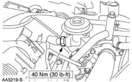
15. Connect the EGR tube.
16. Install the power steering pump.
17. Install the water pump pulley.
18. Install the crankshaft pulley. For additional information, refer to Crankshaft Pulley in this section.
19. Drain the engine oil and fill with clean engine oil.
20. Fill the engine cooling system. For additional information, refer to Section.
21. Connect the battery ground cable. For additional information, refer to Section.
 Removal
1. Disconnect the battery ground cable. For additional information, refer
to Section.
2. Drain the engine cooling system. For additional information, refer to
Section .
3. Remove the crankshaf ...
 Rocker Arm
Removal
CAUTION: If removing more than one rocker arm (6564), mark the
components removed
for correct location.
1. Remove the valve covers. For additional information, refer to
Valve Cover-LH ...
Other materials:
Body System (Diagnosis and Testing)
Inspection and Verification
Leaks
NOTE: Trim will reveal the location of most leaks.
1. Remove any trim or carpet in the general area of the leak.
2. Road test or water test the vehicle.
3. Inspect for a dust pattern around the area in question. In ...
Bushing - Stabilizer Bar
Removal
CAUTION: Suspension fasteners are critical parts because they affect
performance of vital
components and systems and their failure can result in major service expense. A
new part with
the same part number or an equivalent part must be installed, if i ...
Spindle
Special Tool(s)
Tie-Rod End Remover
211-001 (TOOL-3290-D) or
Equivalent
Removal
CAUTION: Suspension fasteners are critical parts because they affect
performance of vital
components and systems and their failure can result in major service expen ...
