Ford Mustang (1999-2004) Service Manual: Removal
1. Disconnect the battery ground cable. For additional information, refer to Section.
2. Drain the engine cooling system. For additional information, refer to Section .
3. Remove the crankshaft pulley. For additional information, refer to Crankshaft Pulley in this section.
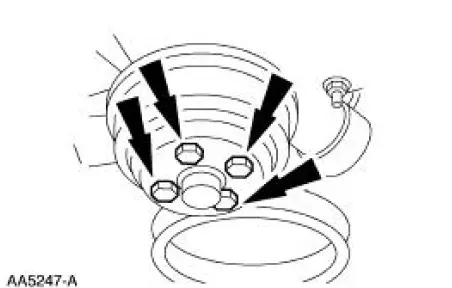
4. Remove the water pump pulley.
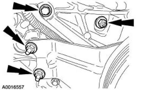
5. Remove the retainers and position the power steering pump aside.
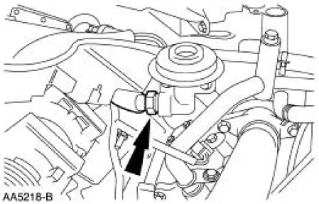
6. Disconnect the exhaust gas recirculation (EGR) tube.
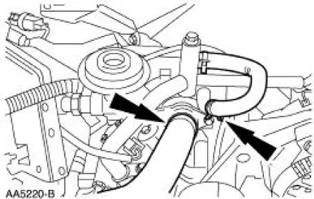
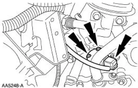
7. Disconnect the upper radiator hose and the bypass hose.
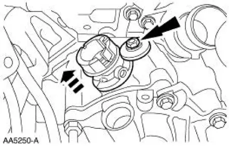
8. Remove the camshaft position (CMP) sensor.
9. Remove the heater water outlet tube. For additional information, refer to Section.
10. Remove the camshaft synchronizer assembly.
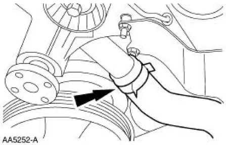
11. Disconnect the lower radiator hose.
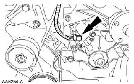
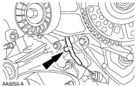
12. Disconnect the crankshaft position sensor electrical connector.
13. Remove the wiring harness pin-type retainer.
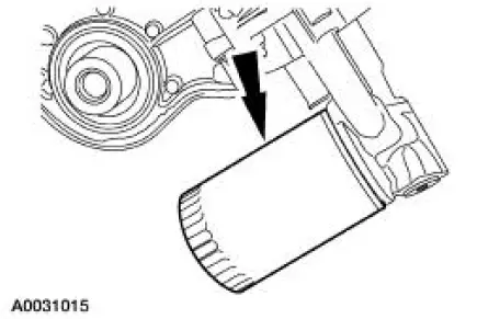
14. Remove the oil filter.
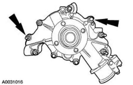
15. Remove the retainers and the water pump.
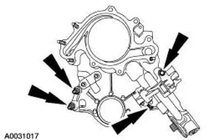
16. CAUTION: The cap screw is hidden; make sure to remove it or the engine front cover will be damaged.
NOTE: Record the location, type and size of the fasteners.
Remove the engine front cover.
- Slide the engine front cover off the two dowels.
- Remove and discard the engine front cover gasket.
 Engine Front Cover
Material
...
 Installation
1. CAUTION: In order to prevent foreign material from contaminating
the engine block
or the engine front cover it is necessary to seal the coolant and oil
passages of both
components. Failure to ...
Other materials:
Removal
1. Remove the rear exterior trim mouldings.
2. Remove the clips
3. Remove the 13 Torx screws and the seal compression panel.
4. Remove the staples.
5. Remove the staples from the number one bow.
6. Remove the rear rail weatherstrip retainers from ea ...
Symptom Chart
Condition
Possible Sources
Action
Hard Steering or
Lack of Assist
Seized lower steering
column shaft U-joints.
Damaged, fractured
steering column
bearing(s).
Power steering pump.
Suspension
components.
...
Charging System (Description and Operation)
The charging system is a negative ground system consisting of the
following:
generator
internal voltage regulator
charging system warning indicator
storage battery
necessary wiring and cables
The generator is belt-driven by the engine ...
