Ford Mustang (1999-2004) Service Manual: Installation
1. CAUTION: The timing chain procedures must be followed exactly or damage to the valve and pistons will result.
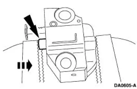
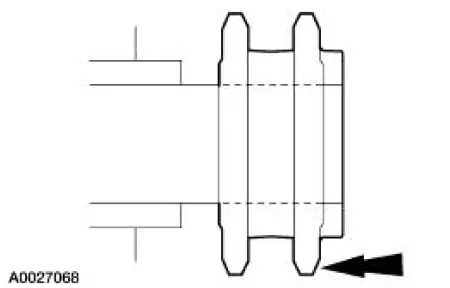
Compress the tensioner plunger, using an edge of a vise.
2. While holding the ratchet mechanism, push the ratchet arm back into the tensioner housing.
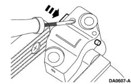
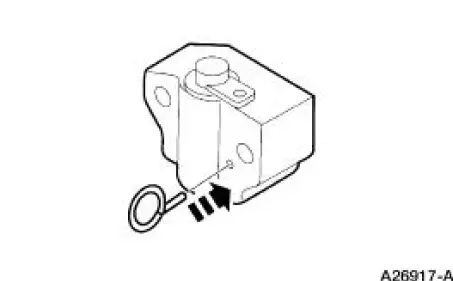
3. Install a paper clip into the hole in the tensioner housing to hold the ratchet assembly and plunger in during installation.
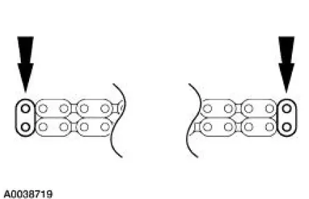
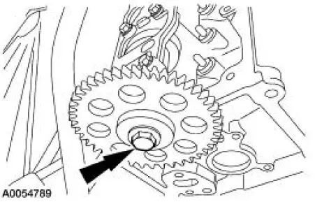
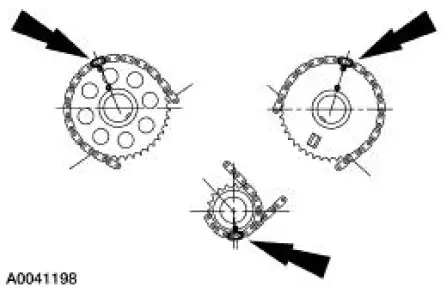
4. If the copper links are not visible, mark one link on one end and one link on the other end, and use as timing marks.
5. Install the camshaft sprockets and new bolts. Tighten the bolts in two stages.
- Stage 1: Tighten the bolt to 40 Nm (30 lb-ft).
- Stage 2: Tighten the bolt an additional 90 degrees (1/4 turn).
6. Remove the special tool.
7. Using the special tool, position the crankshaft so the number one cylinder is at TDC.
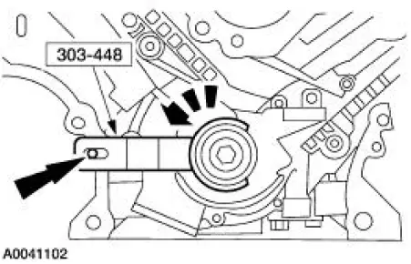
8. Remove the special tool.
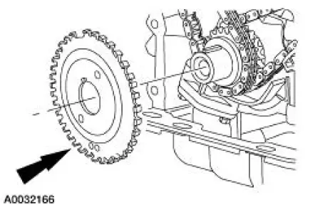
9. Install the crankshaft sprocket, making sure the flange faces forward.
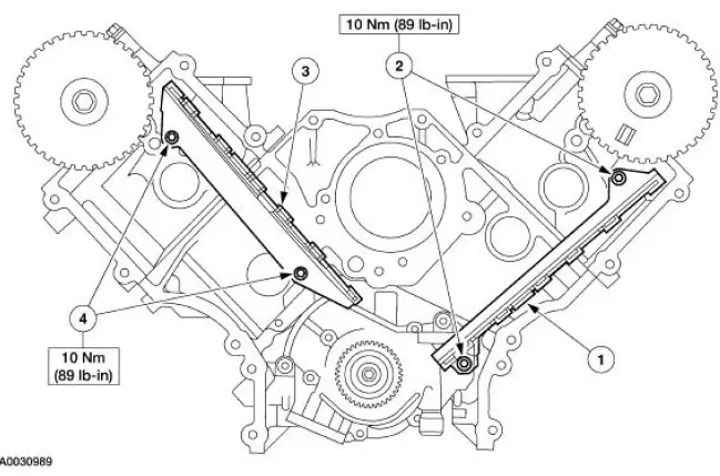
10. Install the timing chain guide.
1. Position the LH timing chain guide.
2. Install and tighten the LH bolts.
3. Position the RH timing chain guide.
4. Install and tighten the RH bolts.
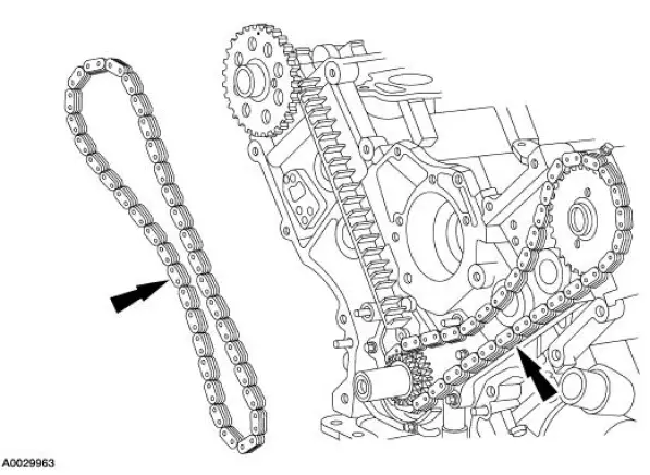
11. Install the timing chains.
- Install the LH (inner) timing chain on the crankshaft sprocket, aligning the copper link with the dot on the crankshaft sprocket.
- Install the LH (inner) timing chain on the camshaft sprocket, aligning the copper link with the dot on the camshaft sprocket.
- Install the RH (outer) timing chain on the crankshaft sprocket, aligning the copper link with the dot on the crankshaft sprocket.
- Install the RH (outer) timing chain on the camshaft sprocket, aligning the copper link with the dot on the camshaft sprocket.
12. Make sure that the copper (marked) chain links are lined up with the dots on the crankshaft sprocket and the camshaft sprockets.
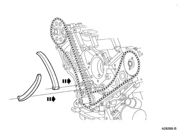
13. NOTE: The LH timing chain tensioner arm has a bump near the dowel hole, for identification.
Position the LH and the RH timing chain tensioner arm on the dowel pins.
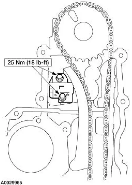
14. Position the RH timing chain tensioner and install the bolts.
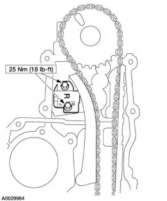
15. Position the LH timing chain tensioner and install the bolts.
16. Remove the paper clip from the RH and the LH timing chain tensioners.
17. NOTE: Rotate the camshaft to the base circle of the camshaft lobe before installing the roller followers.
NOTE: Keep all the roller followers in order when installing.
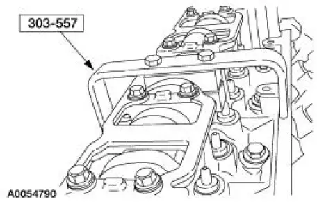
Using the special tool, install the 16 roller followers.
18. Install the eight spark plugs.
19. Install the eight ignition coils and bolts.
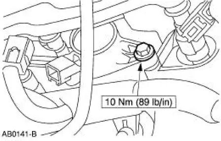
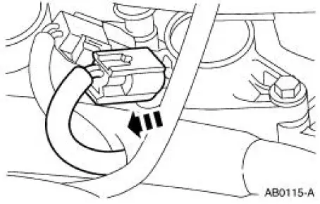
20. Connect the eight ignition coil electrical connectors.
21. Install the crankshaft sensor ring on the crankshaft.
22. Install the engine front cover. For additional information, refer to Engine Front Cover in this section.
 Removal
CAUTION: Since the engine is not free-wheeling, timing procedures must
be followed
exactly or piston and valve damage can occur.
1. Remove the engine front cover. For additional information, refer to ...
 Valve Seals
Special Tool(s)
Valve Spring Compressor
303-452 (T93P-6565-AR)
Valve Stem Seal Replacer
303-383 (T91P-6571-A)
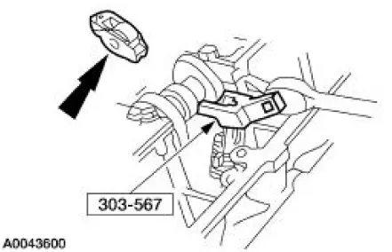
Compressor, Valve Spring
(Exhaust)
303-567 (T97 ...
Other materials:
Ignition Coil
Material
Item
Specification
Silicone Brake Caliper Grease
and Dielectric Compound
D7AZ-19A331-A or equivalent
ESE-M1C171-
A
Removal and Installation
1. Disconnect the battery ground cable (14301). For additional
information, refer to ...
External Controls (Diagnosis and Testing)
Refer to Wiring Diagrams Cell 37 , Shift Lock for schematic and connector
information.
Refer to Wiring Diagrams Cell 29 , Transmission Control for schematic and
connector information.
Special Tool(s)
73 Digital Multimeter
105-R0051 or equivalent ...
Installation
1. Overlay the new rear window glass assembly over the old rear
window glass assembly and
transpose the markings with a grease pencil.
2. Center the V-notch on the new rear window glass assembly to the
center mark on the top of the
number four bow ...
