Ford Mustang (1999-2004) Service Manual: Removal
CAUTION: Since the engine is not free-wheeling, timing procedures must be followed exactly or piston and valve damage can occur.
1. Remove the engine front cover. For additional information, refer to Engine Front Cover in this section.
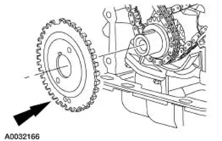
2. Remove the crankshaft sensor ring from the crankshaft.
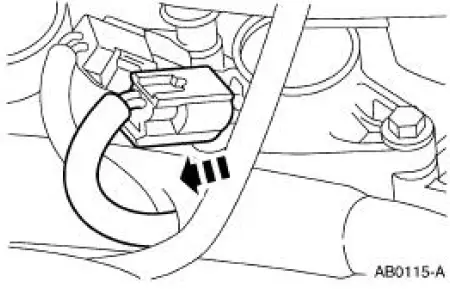
3. Disconnect the eight ignition coil electrical connectors.
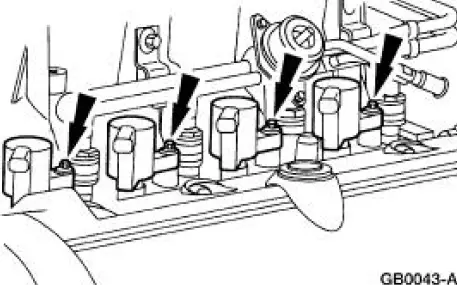
4. Remove the bolts and the eight ignition coils.
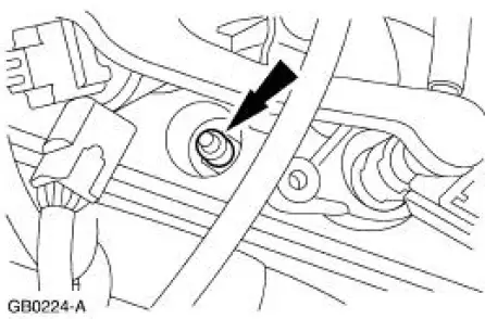
5. NOTE: Use compressed air to remove any foreign material from the spark plug wells before removing the spark plugs.
Remove the spark plugs.
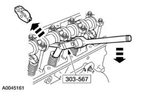
6. NOTE: Rotate the camshaft to the base circle of the camshaft lobe before removing the followers. Keep the roller followers in order when removing.
Using the special tool, remove the 16 roller followers.
- Rotate the crankshaft and camshaft as necessary.
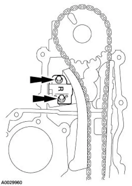
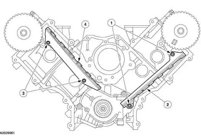
7. Remove the bolts and the LH timing chain tensioner.
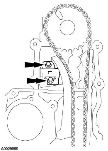
8. Remove the bolts and the RH timing chain tensioner.
9. Remove the LH and the RH timing chain tensioner arm from the dowel pins.
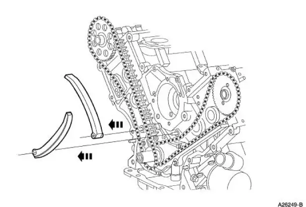
10. Remove the timing chains and the crankshaft sprocket.
11. Remove the timing chain guides.
1. Remove the bolts.
2. Remove the LH timing chain guide.
3. Remove the bolts.
4. Remove the RH timing chain guide.
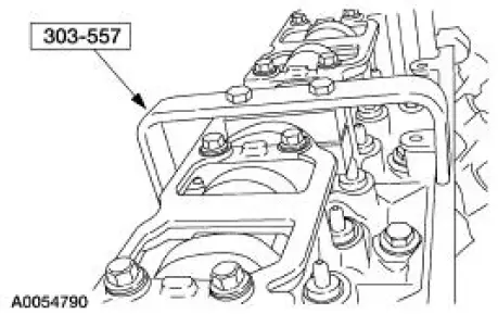
12. NOTE: RH shown, LH similar.
Install the special tool.
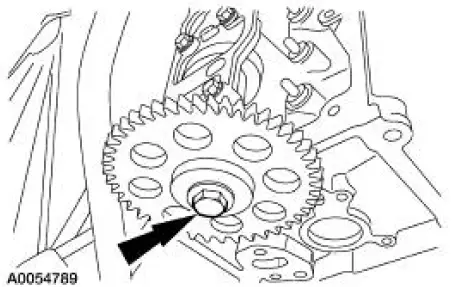
13. NOTE: RH shown, LH similar.
Remove the bolt and the camshaft gear.
 Timing Drive Components
Special Tool(s)
Compressor, Valve Spring
303-567 (T97P-6565-AH)
Holding Tool, Crankshaft
303-448 (T93P-6303-A)
Aligner, Camshaft Position
303-557 (T96T-6256-B) ...
 Installation
1. CAUTION: The timing chain procedures must be followed exactly or
damage to the
valve and pistons will result.
Compress the tensioner plunger, using an edge of a vise.
2. While holding the ratch ...
Other materials:
Manual
WARNING: Brake fluid contains polyglycol ethers and polyglycols.
Avoid contact with
eyes. Wash hands thoroughly after handling. If brake fluid contacts
eyes, flush eyes with
running water for 15 minutes. Get medical attention if irritation
persist ...
Changing the vehicle battery
WARNING: Batteries normally produce explosive gases which
can cause personal injury. Therefore, do not allow flames, sparks
or lighted substances to come near the battery. When working near the
battery, always shield your face and protect your eyes. Always pro ...
Transmission Draining and Filling
Material
Item
Specification
DEXRON III (ATF)
Transmission Fluid
XT-2-QDX
DEXRON III
1. Remove the drain plug and drain the transmission.
Position a suitable drain pan under the transmission.
2. Clean and install the drain plug.
3. N ...
