
Ford Mustang (1999-2004) Service Manual: Timing Drive Components
Special Tool(s)
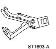 |
Compressor, Valve Spring 303-567 (T97P-6565-AH) |
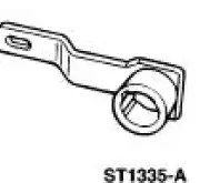 |
Holding Tool, Crankshaft 303-448 (T93P-6303-A) |
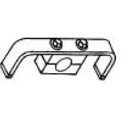 |
Aligner, Camshaft Position 303-557 (T96T-6256-B) |
 Installation
1. Apply silicone gasket and sealant in the locations shown.
2. Install the engine front cover.
3. Install the belt idler pulleys and the bolts.
4. Connect the CMP sensor electrical conn ...
 Removal
CAUTION: Since the engine is not free-wheeling, timing procedures must
be followed
exactly or piston and valve damage can occur.
1. Remove the engine front cover. For additional information, refer to ...
Other materials:
General information
WARNING: Driving while distracted can result in loss of vehicle
control, accident and injury. Ford strongly recommends that drivers
use extreme caution when using any device or feature that may take their
focus off the road. Your primary responsibility is the ...
Ignition Switch
Removal
1. Disconnect the battery ground cable.
2. Remove the lower instrument panel steering column cover.
1. Remove the screws.
2. Remove the lower instrument panel steering column cover.
3. Remove the instrument panel reinforcement.
1. Rem ...
Output Shaft
Special Tool(s)
Puller, Bearing
205-D064 (D84L-1123-A)
Adapter for 303-224 (Handle)
205-153 (T80T-4000-W)
Installer, Output Shaft Rear
Bearing
308-401
Remover/Installer, Bearing
Tube
308-025 (T75L-7025 ...
