Ford Mustang (1999-2004) Service Manual: Valve Seals
Special Tool(s)
 |
Valve Spring Compressor 303-452 (T93P-6565-AR) |
 |
Valve Stem Seal Replacer 303-383 (T91P-6571-A) |
 |
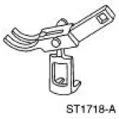
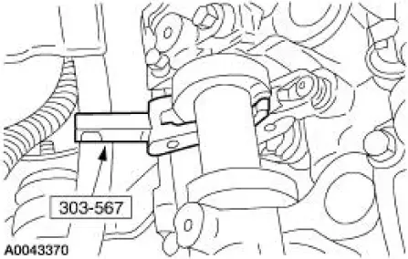
Compressor, Valve Spring (Exhaust) 303-567 (T97P- 6565-AH) |
Material
| Item | Specification |
| Super Premium SAE 5W-20 Motor Oil XO-5W20-QSP | WSS-M2C153- H |
Removal and Installation
1. Remove the roller followers. For additional information, refer to Camshaft Roller Follower in this section.
2. Remove the spark plug (12405) from the applicable cylinder.
3. Position the piston (6102) of the cylinder being serviced at the bottom of the stroke.
4. CAUTION: If air pressure has forced the piston to the bottom of the cylinder, any loss of air pressure will allow the valve to fall into the cylinder. If air pressure must be removed, support the valve prior to removal.
Use compressed air in the cylinder to hold both valves in position.
5. Using the special tool, compress the valve spring (6513).
6. NOTE: Valve stem seals should be visually inspected if not installing new seals.
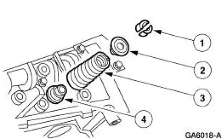
Remove the valve stem seals.
1. Remove the valve spring retainer keys.
2. Remove the valve spring retainers.
3. Remove the valve springs.
4. Remove the valve stem seals.
7. NOTE: Lubricate the lip of the new seal with clean engine oil prior to installation.
To install, reverse the removal procedure.
 Installation
1. CAUTION: The timing chain procedures must be followed exactly or
damage to the
valve and pistons will result.
Compress the tensioner plunger, using an edge of a vise.
2. While holding the ratch ...
 Hydraulic Lash Adjuster
Removal and Installation
1. Remove the roller followers. For additional information, refer to Camshaft
Roller Follower in this
section.
2. Remove the eight hydraulic lash adjusters.
3. Inspect the ...
Other materials:
Principles of Operation
Battery Saver
The battery saver feature provides automatic shut-off of power to demand
and courtesy lamp circuitry.
When the generic electronic module (GEM) detects the ignition switch
circuits are in the key OFF or
removed ignition key positions, powe ...
Removal
CAUTION: Suspension fasteners are critical parts because they affect
performance of vital
components and systems and their failure can result in major service expense. A
new part with
the same part number must be installed if installation becomes necessary. ...
Road Test
Verify the customer concern by carrying out a road test on a smooth road. If
any vibrations are
apparent.
To maximize tire performance, inspect for signs of incorrect inflation and
uneven wear, which may
indicate a need for balancing, rotation, or front susp ...
