Ford Mustang (1999-2004) Service Manual: Installation
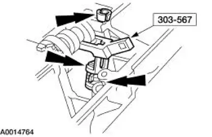
1. Using the special tools, install the new intake valve stem seals.
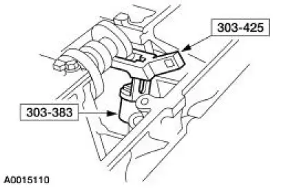
2. Using the special tools, install the new exhaust valve stem seals.
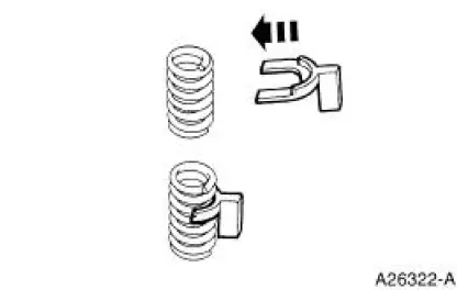
3. Install the Valve Spring Compressor Spacer between the valve spring coils to protect the intake valve stem seal from damage.
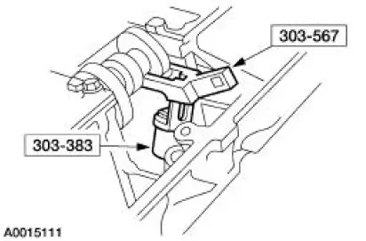
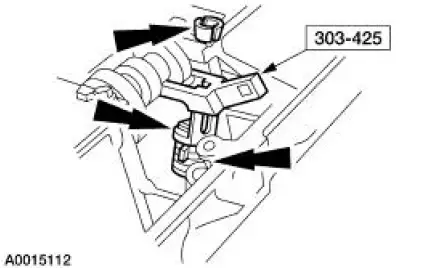
4. Using the special tool, install the intake valve spring, the spring retainer and the valve spring retainer keys.
5. Install the Valve Spring Compressor Spacer between the valve spring coils to protect the intake valve stem seal from damage.
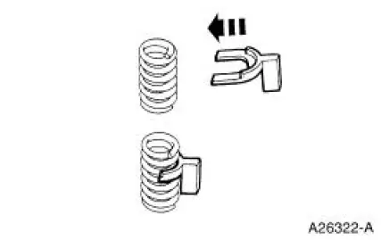
6. Using the special tool, install the exhaust valve spring, the spring retainer and the valve spring retainer keys.
7. Remove the compressed air hose from the cylinder.
8. Install the spark plugs. For additional information, refer to Section.
9. Install the roller followers. For additional information, refer to Roller Followers in this section.
 Removal
1. Remove the roller followers. For additional information, refer to Roller
Followers in this section.
2. Remove the spark plugs. For additional information, refer to Section .
3. Position the pist ...
 Hydraulic Lash Adjusters
Removal
1. Remove the roller followers. For additional information, refer to Roller
Followers in this section.
2. Remove the 16 hydraulic lash adjusters.
3. Inspect the roller followers. For addit ...
Other materials:
Battery (Removal and Installation)
Removal and Installation
WARNING: Batteries normally produce explosive gases which can
cause personal injury.
Therefore, do not allow flames, sparks or lighted substances to come
near the battery. When
charging or working near a battery, always sh ...
Exhaust Manifold to Exhaust Gas Recirculation (EGR)
Valve Tube - Cobra
Removal and Installation
1. Remove the EGR valve. For addditional information, refer to Exhaust
Gas Recirculation (EGR)
Valve-Cobra in this section.
2. With the vehicle in NEUTRAL, position it on a hoist.
3. Disconnect the exhaust manifold to EGR valve ...
Motor - Window Regulator
Removal
1. Remove the door trim panel. For additional information, refer to
Section.
2. Remove the screws and the speaker.
3. Disconnect the electrical connector.
4. Remove the screws and the window regulator motor.
Installation
1. To install, ...
