Ford Mustang (1999-2004) Service Manual: Removal
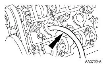
1. Remove the roller followers. For additional information, refer to Roller Followers in this section.
2. Remove the spark plugs. For additional information, refer to Section .
3. Position the piston of the cylinder being serviced at the bottom of the stroke.
4. CAUTION: If air pressure has forced the piston to the bottom of the cylinder any loss of air pressure will allow the valve to fall into the cylinder. If air pressure must be removed support the valve prior to removal.
Use compressed air in the cylinder to hold both valves in position.
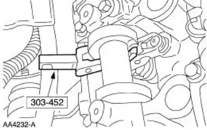
5. Using the special tool, compress the intake valve spring.
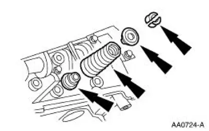
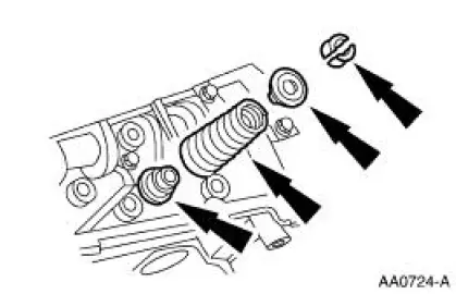
6. NOTE: Valve stem seals should be visually inspected if new seals are not installed.
Remove the valve spring retainer keys, the valve spring retainer, the valve spring and the valve stem seal.
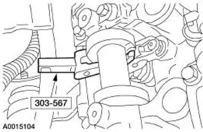
7. Using the special tool, compress the exhaust valve spring.
8. NOTE: Valve stem seals should be visually inspected if new seals are not installed.
Remove the valve spring retainer keys, the valve spring retainer, the valve spring and the valve stem seal.
 Valve - Springs, Retainer and Valve Stem Seal
Special Tool(s)
Compressor, Valve Spring
303-452 (T93P-6565-AR)
Installer, Valve Stem Oil Seal
303-383 (T91P-6571-A)
Compressor, Valve Spring
303-567 (T97P- ...
 Installation
1. Using the special tools, install the new intake valve stem seals.
2. Using the special tools, install the new exhaust valve stem seals.
3. Install the Valve Spring Compressor Spacer between the ...
Other materials:
Lifting
CAUTION: Do not allow the lift adapters to contact the steering
linkage, suspension arms,
stabilizer arms, or to compress the lower suspension arm stabilizer bar
insulator (5493).
Damage to the suspension, exhaust and steering linkage components may occur i ...
Inflating your tires
Safe operation of your vehicle requires that your tires are properly
inflated. Remember that a tire can lose up to half of its air pressure
without appearing flat.
Every day before you drive, check your tires. If one looks lower than the
others, use a tire ga ...
Wiper Blade and Pivot Arm Adjustment
1. Cycle and park the windshield wipers.
2. Verify that the distance between the center of the RH windshield
wiper blade and the top edge
of the cowl top vent panel is within specification.
3. Verify that the distance between the center of the LH win ...
