Ford Mustang (1999-2004) Service Manual: Hydraulic Lash Adjusters
Removal
1. Remove the roller followers. For additional information, refer to Roller Followers in this section.
2. Remove the 16 hydraulic lash adjusters.
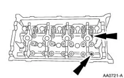
3. Inspect the roller followers. For additional information, refer to Section.
Installation
1. To install, reverse the removal procedure.
 Installation
1. Using the special tools, install the new intake valve stem seals.
2. Using the special tools, install the new exhaust valve stem seals.
3. Install the Valve Spring Compressor Spacer between the ...
 Roller Followers
Special Tool(s)
Compressor, Valve Spring
303-452 (T93P-6565-AR)
Removal and Installation
1. Remove the LH and RH valve cover. For additional information, refer to
Valve Cover LH and
...
Other materials:
Axle
Special Tool(s)
2-Jaw Puller
205-D072 (D97L-4221-A) or
equivalent
Adapter for 205-S127
205-105 (T76P-4020-A3)
Bearing Preload Tool
205-395 (T93P-4220-A)
Plate, Bearing/Oil Seal
205-090 (T75L-1165-B)
Gauge, ...
Removal
1. Remove the rear defrost connectors if necessary.
2. Remove the nuts retaining the well sling and convertible top tacking
strips.
3. Remove the three tacking strips.
4. Mark the top of the convertible top skin around the top of all three
tacking s ...
Fittings - R-Clip
Material
Item
Specification
SAE 5W-20 Super Premium
Synthetic Blend Motor Oil
XO-5W20-QSP or equivalent
WSS-M2C153-
H
Disconnect
WARNING: Do not smoke or carry lighted tobacco or open flame of any
type when
working on or near any fuel- ...
