Ford Mustang (1999-2004) Service Manual: Key Programming - Enable/Disable Spare Key Programming
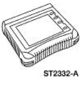
Special Tool(s)
 |
Worldwide Diagnostic System (WDS) 418-F224, New Generation STAR (NGS) Tester 418-F052, or equivalent diagnostic tool |
NOTE: The spare key programming switch is a diagnostic tool programmable switch that provides the capability to enable/disable the spare key programming procedure. This procedure is in the Owners Guide spare key programming procedure or in this section under Key Programming-Program a Key Using Two Programmed Keys . This programmable switch is provided as a convenience for rental company fleets or other fleet purchasers who may not want the spare key programming procedure available to the vehicle driver.
NOTE: The spare key programming switch state can be viewed by instrument cluster PID SPARE_KY.
1. Insert a programmed ignition key into the ignition lock cylinder and turn the ignition switch to RUN.
2. Enter diagnostic tool. Follow the SECURITY ACCESS PROCEDURE. For additional information, refer to Security Access-Procedure to obtain security access.
3. NOTE: The default setting on delivery of all new vehicles is <ENABLE>.
From diagnostic tool menu, select SPARE KEY PROGRAMMING SWITCH selection to the desired setting: <ENABLE> Spare key programming procedure is accessible.
<DISABLE> Spare key programming procedure is not accessible.
 Key Programming - Program a Key Using Two
Programmed Keys
Special Tool(s)
Worldwide Diagnostic System
(WDS)
418-F224,
New Generation STAR (NGS)
Tester
418-F052, or equivalent
diagnostic tool
NOTE: This procedure only works if two or ...
 Key Programming - Additional Key With One Programmed
Key
Special Tool(s)
Worldwide Diagnostic System
(WDS)
418-F224,
New Generation STAR (NGS)
Tester
418-F052, or equivalent
diagnostic tool
NOTE: This procedure is used when a custo ...
Other materials:
Display mode
You can choose to turn your screen on or off and if you would like to
view the status bars on the top and bottom of the screen. Press DISP to
see the options.
Display Mode Voice Commands
The following voice commands are available in display mode.
If you are ...
Seats (Description and Operation)
Seats - Front Power
The front power seat features:
a six-way seat regulator control switch (14A701) located on the
front of the seat.
a seat track (61705) mounted under the seat.
a seat regulator motor (14547) and gear housing mounted on ...
Piston
Special Tool(s)
Piston Pin Tool or equivalent
303-D034 (D81L-6135-A)
Material
Item
Specification
SAE 5W-20 Premium Synthetic
Blend Motor Oil
XO-5W20-QSP or equivalent
WSS-M2C153-
H
Disassembly
1. Using the special tool, ...
