Ford Mustang (1999-2004) Service Manual: Key Programming - Additional Key With One Programmed Key
Special Tool(s)
 |
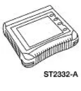
Worldwide Diagnostic System (WDS) 418-F224, New Generation STAR (NGS) Tester 418-F052, or equivalent diagnostic tool |
NOTE: This procedure is used when a customer needs to have an additional key programmed into the vehicle without erasing stored key codes, but does not have two programmed keys available. This procedure is also useful when attempting to determine if an ignition key is defective, as a new key can be installed without erasing keys or without having two programmed keys available.
NOTE: Before programming, the new key must have the correct mechanical cut for the ignition lock.
NOTE: If eight keys are already programmed, this procedure will not allow any further ignition keys to be programmed without erasing all stored key codes first. The number of keys programmed into the system can be determined using the PID NUMKEYS.
1. Turn the ignition switch from the OFF position to the RUN position using the new, unprogrammed ignition key.
2. Enter diagnostic tool using the Ford Service Function (FSF) card and enter the appropriate instrument cluster. Follow Security Access to obtain security access. For additional information, refer to Security Access-Procedure .
3. From the diagnostic tool menu Select: IGNITION KEY CODE PROGRAM.
4. Turn the ignition switch to the OFF position and disconnect diagnostic tool.
5. Attempt to start the engine with the new ignition key. The vehicle engine should start and run normally.
 Key Programming - Enable/Disable Spare Key
Programming
Special Tool(s)
Worldwide Diagnostic System
(WDS)
418-F224,
New Generation STAR (NGS)
Tester
418-F052, or equivalent
diagnostic tool
NOTE: The spare key programming switch is ...
 Security Access - Procedure
Special Tool(s)
Worldwide
418-F224,
New Generation STAR (NGS)
Tester
418-F052, or equivalent
diagnostic tool
NOTE: The security access procedure is utilized to obtain passive a ...
Other materials:
Wheel Hub - Cobra
Special Tool(s)
2-3 Jaw Puller
205-D026 (D80L-1013-A) or
Equivalent
Driver
205-199 (T83T-3132-A1)
Front Hub Remover Replacer
204-069 (T81P-1104-C)
Hub Bearing Remover
204-081 (T83P-1104-AH2)
...
Latch - Luggage Compartment Lid
Removal
1. NOTE: The luggage compartment lid latch is equipped with
mechanical interior release handle.
Disconnect the luggage compartment lid lock actuator (432A38) cable.
2. Remove the luggage compartment lid latch (43200).
1. Disconnect the ...
Speed Control (Diagnosis and Testing)
Refer to Wiring Diagrams Cell 31 , Speed Control for schematic and connector
information.
Special Tool(s)
Worldwide Diagnostic System
(WDS)
418-F224,
New Generation STAR (NGS)
Tester
418-F052, or equivalent
diagnostic tool
7 ...
