Ford Mustang (1999-2004) Service Manual: Key Release Button
Removal
1. Disconnect the battery ground cable.
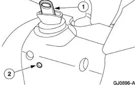
2. Remove the ignition switch lock cylinder.
1. Insert the ignition key into the ignition switch lock cylinder and turn to RUN position.
2. Push the ignition switch lock cylinder release tab with a punch while pulling out the ignition switch lock cylinder.
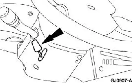
3. Remove the tilt wheel handle.
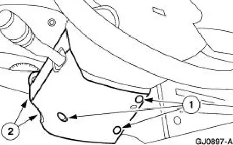
4. Remove the upper and lower steering column shrouds.
1. Remove the screws.
2. Remove the upper and lower steering column shrouds.
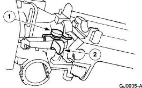
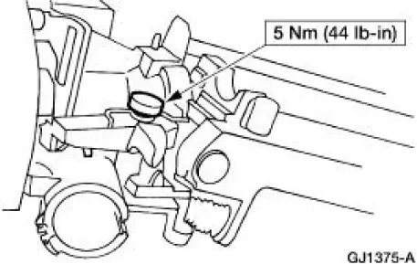
5. Remove the key release button.
1. Remove the key release button bolt.
2. Remove the release button handle and the spring.
Installation
1. NOTE: When the battery is disconnected and reconnected, some abnormal drive symptoms may occur while the vehicle relearns its adaptive strategy. The vehicle may need to be driven 16 km (10 mi) or more to relearn the strategy.
To install, reverse the removal procedure.
 Ignition Switch
Removal
1. Disconnect the battery ground cable.
2. Remove the lower instrument panel steering column cover.
1. Remove the screws.
2. Remove the lower instrument panel steering column cover.
...
 Engine
...
Other materials:
Removal
WARNING: Always wear safety glasses when repairing an air bag
supplemental restraint
system (SRS) vehicle and when handling an air bag module. This will
reduce the risk of injury
in the event of an accidental deployment.
WARNING: Carry a live air ...
Interior mirror
WARNING: Do not adjust the mirror when your vehicle is
moving.
Note: Do not clean the housing or glass of any mirror with harsh
abrasives, fuel or other petroleum or ammonia based cleaning products.
You can adjust the interior mirror to your preference. Some ...
Assembly
All steering gears
1. Install the steering gear in the special tools.
Steering gears equipped with travel restrictors
2. Install the travel restrictors.
Install new travel restrictors as necessary.
All steering gears
3. CAUTION: Place the steering gear at t ...
