Ford Mustang (1999-2004) Service Manual: Clutch Controls (Description and Operation)
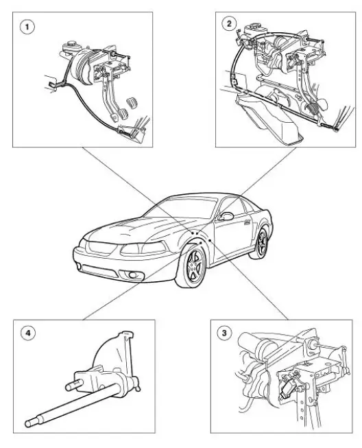
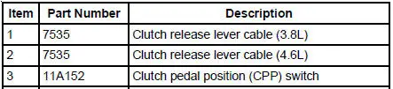

The clutch control system engages and disengages the clutch. The clutch control system disengages the clutch when the clutch pedal is depressed and engages the clutch when the clutch pedal is released. Clutch pedal motion is transmitted by the clutch release lever cable to the clutch release lever. The clutch release hub and bearing engages the clutch pressure plate diaphragm spring, releasing the pressure on the clutch disc which in turn disengages the transmission from the engine.
The clutch adjusts automatically to compensate for clutch disc wear. The clutch linkage is selfadjusting.
The clutch pedal position (CPP) switch prevents the starter motor from engaging unless the clutch pedal is depressed all the way to the floor. The switch plunger is contacted by the clutch pedal and extends as the clutch pedal is pressed. The clutch pedal position switch is electrically connected in line with the ignition switch and the starter motor relay coil. The CPP also turns off the speed control when the clutch pedal is depressed.
 Clutch Controls
General Specifications
Torque Specifications
...
 Clutch Pedal - Quadrant and Pawl Assembly
Removal
1. Disconnect the battery ground cable (14301).
2. Loosen the nut from inside the engine compartment.
3. Loosen the nuts from inside the vehicle.
4. Loosen the screw.
5. Disconnect t ...
Other materials:
Input Shaft and Bearing
Special Tool(s)
Remover, Driver Pinion
Bearing Cone
205-D002 (D79L-4621-A) or
equivalent
Installer, Drive Pinion Bearing
Cone
205-011 (T57L-4621-B)
Remover/Installer, Bearing
Tube
308-024 (T75L-7025-B)
Disas ...
Inspection and Verification
NOTE: If any concerns are noted with the speedometer, stoplamps, or
horn, address those concerns
by referring to their associated sections before continuing speed control
diagnosis.
1. Verify the customer concern by operating the speed control system.
2. Vi ...
Crankshaft Rear Oil Seal
Special Tool(s)
Installer, Crankshaft Rear Oil
Seal
303-518 (T95P-6701-DH)
Remover, Crankshaft Rear Oil
Seal
303-519 (T95P-6701-EH)
Installer, Crankshaft Rear Oil
Seal
303-516 (T95P-6701-BH)
Remover ...
