Ford Mustang (1999-2004) Service Manual: Lifting
CAUTION: Do not allow the lift adapters to contact the steering linkage, suspension arms, stabilizer arms, or to compress the lower suspension arm stabilizer bar insulator (5493).
Damage to the suspension, exhaust and steering linkage components may occur if care is not exercised when positioning the hoist adapters prior to lifting the vehicle.
CAUTION: Never use the differential housing as a lift point. Damage to the differential housing and cover may occur.
CAUTION: Do not lift vehicle on rocker panel pinch flange or convertible cross brace.
Body damage may occur.
Lift the vehicle using the Lifting Points procedure in this section.
Lifting Points-Drive On Lift
CAUTION: To prevent possible damage to the underbody, do not drive the vehicle onto the drive on lift without first checking for possible interference.
Check for interference between the upright flanges of the hoist rails and the underbody.
If an interference exists, modify the hoist flanges or build up the approach ramps as necessary to provide clearance.
Lifting Points-Frame Contact Lift, Single Post Lift, Two Post Lift
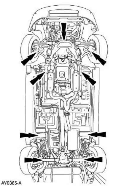
CAUTION: Do not position lift pads under the No. 3 crossmember.
CAUTION: Do not lift vehicle on rocker panel pinch flange or convertible cross brace.
Body damage may occur.
NOTE: Adapters may be necessary to clear vehicle components to lift the vehicle safely. The adapters must be placed at the four designated contact points. Position the adapters so they are center on the adapter contact area.
Lift the vehicle at the applicable lift points.
 Jacking
WARNING: Never run the engine with one wheel off the ground, such as
when changing a
tire. The wheel still on the ground could cause the vehicle to move.
CAUTION: The jack (17080) provided with the v ...
 Maintenance Schedule
Maintenance Schedule -Vehicles with Gasoline Engines
The maintenance schedule is designed to protect against major repairs
resulting from neglect or
inadequate maintenance and to prolong the life of ...
Other materials:
Engine - Mach I 4.6L (4V)
General Specifications
Engine Specifications
a - Newly Installed-Refers to the condition of the "NEW" drive belt
before the engine has made no more
than one rotation and before the belt has had a chance to stretch or seat
into the pu ...
Creating a MyKey
Use the information display to create a MyKey.
For Type 1 information displays:
1. Insert the key you want to program into the ignition.
2. Switch the ignition on.
3. Access the main menu within the information display, and press
SETUP using the information d ...
HomeLink® wireless control system
WARNING: Make sure that the garage door and security device
are free from obstruction when you are programming. Do not
program the system with the vehicle in the garage.
WARNING: Do not use the system with any garage door opener
that does not have the safety s ...
