Ford Mustang (1999-2004) Service Manual: Rear Suspension
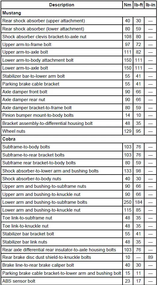
Torque Specifications

WARNING: All vehicles are equipped with gas pressurized shock absorbers which will extend unassisted. Do not apply heat or flame to the shock absorbers during removal or component servicing. Failure to follow these instructions can result in personal injury.
CAUTION: Suspension fasteners are critical parts because they affect performance of vital components and systems and their failure can result in major service expense. A new part with the same part number must be installed if installation becomes necessary. If substitution is necessary, the part must be of the same finish and property class. Torque values must be used as specified during reassembly to make sure of correct retention of these parts.
The rear suspension consists of the following components:
- rear spring (4460)
- rear shock absorber (18125)
- rear upper suspension arm and bushings (5500)
- common LH and RH
- rear lower suspension arm and bushings (5A649)
- common LH and RH
- rear stabilizer bar (5A772) (4.6 2V-equipped models only)
- axle drive line vibration dampers (4.6 2V-equipped models only)
- Rear Suspension (Description and Operation)
- Wheel Hub - Cobra
- Wheel Studs
- Upper Arm
- Upper Arm - Cobra
- Lower Arm
- Stabilizer Bar
- Stabilizer Bar - Cobra
- Link - Stabilizer Bar
- Wheel Knuckle - Cobra
- Toe Link - Cobra
- Spring - Coil
- Spring - Cobra
- Shock Absorber
- Damper
 Installation
1. Install the spring.
1. Position the spring and spring insulator in the front suspension lower
control arm.
2. Swing the arm into the fender well.
2. Position a jack stand under the front su ...
 Rear Suspension (Description and Operation)
Item
Part Number
Description
1
18125
Rear shock absorber
2
-
Rear axle driveline vibration damper
3
5A649
Rear lower suspension arm and bushing (common ...
Other materials:
Bearing Whine
Bearing whine is a high-pitched sound similar to a whistle. It is usually
caused by worn/damaged
pinion bearings, which are operating at driveshaft speed. Bearing noise occurs
at all driving speeds.
This distinguishes it from gear whine which usually comes ...
Installation
All vehicles
1. Position the engine front cover gasket on the engine front cover.
2. NOTE: If the engine front cover is not secured within four minutes, the
sealant must be removed
and the sealing area cleaned with metal surface cleaner. Allow to dry until ...
Parking brake
WARNING: If the parking brake is fully released, but the brake
warning lamp remains illuminated, the brakes may not be
working properly. See your authorized dealer as soon as possible.
WARNING: Always set the parking brake fully and make sure
that the transmis ...
