Ford Mustang (1999-2004) Service Manual: Main Control Valve Body
Special Tool(s)
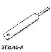 |
Gauge, Transmission Solenoid Connectors 307-426 |
Removal
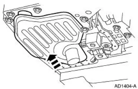
1. Drain transmission fluid and remove the transmission fluid pan and filter. For additional information, refer to Fluid Pan, Gasket and Filter .
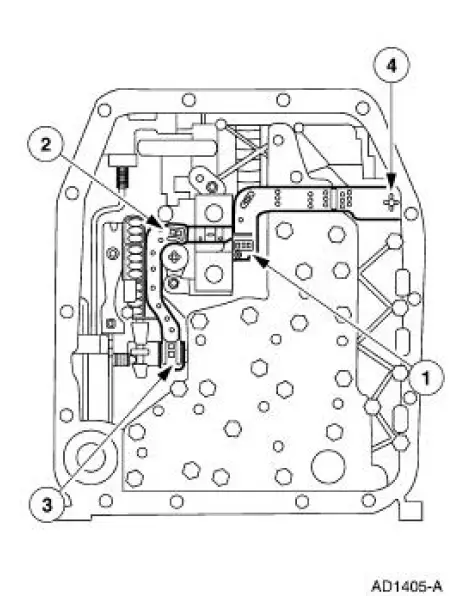
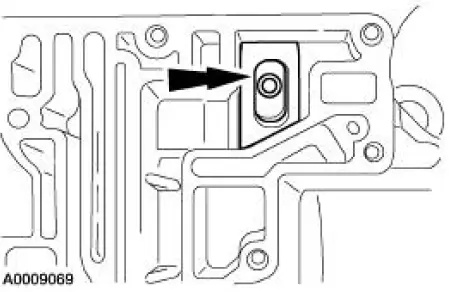
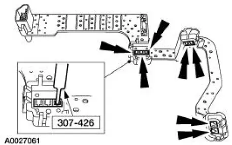
2. CAUTION: Do not pull on the molded lead frame. This may cause damage to the connector ends. Carefully pry up on the locking tabs to disconnect the solenoids.
Disconnect the molded lead frame from the solenoids.
Disconnect the molded lead frame from the solenoids.
1. Disconnect the shift solenoid SSA and SSB.
2. Disconnect the torque converter clutch (TCC).
3. Disconnect the electronic pressure control (EPC) solenoid.
4. Disconnect the bulkhead inter-connector.
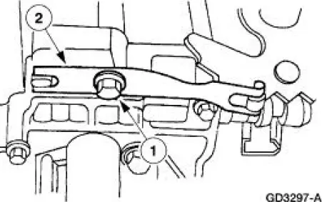
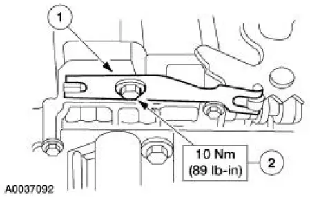
3. Remove the manual control valve detent lever spring.
1. Remove the bolt.
2. Remove the manual control valve detent lever spring.
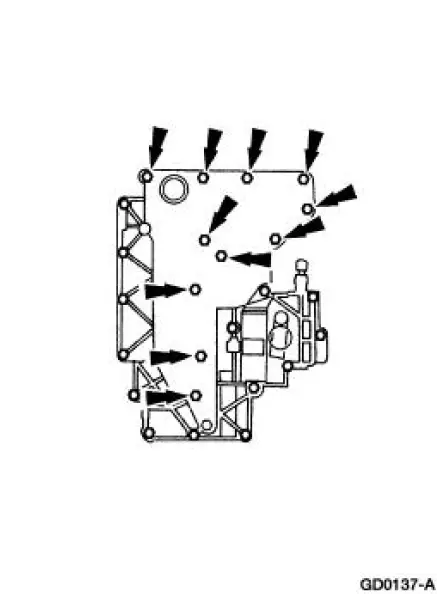
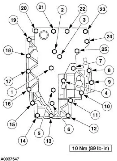
4. Remove the 24 valve body-to-case bolts.
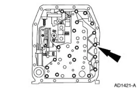
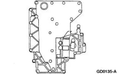
5. Remove the main control valve body and discard the pump outlet screen.
Installation
1. NOTE: Make sure that the drive pin of the manual valve detent lever assembly engages the manual valve in the correct location prior to installing the bolts.
Position the main control valve body gasket and main control valve body using the two alignment bolts as a guide.
2. NOTE: The main control valve body bolts will be tightened in later steps.
Loosely install the bolts.
3. NOTE: The main control valve body bolts will be tightened in later steps.
Loosely install the bolts.
4. Install the manual control valve detent lever spring.
1. Position the manual control valve detent lever spring.
2. Install the bolt.
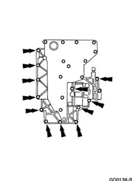
5. Tighten the main control valve body bolts in the sequence shown.
6. Inspect the lead frame for damage.
- Using the special tool, check all lead frame solenoid connections. The gauge should fit tightly and not fall out after being inserted.
- If the special tool passes through any lead frame connector pins or does not feel like it makes a good contact, install a new lead frame.
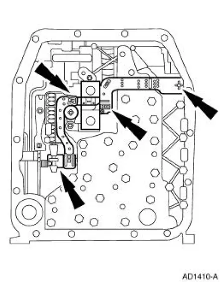
7. Connect the molded lead frame to the solenoids.
- Connect the bulkhead inter-connector by pressing it in place by hand and fully seating the connector in place.
- Connect the EPC solenoid by pressing it in place by hand and fully seating the connector in place. Make sure that the terminals pass fully through the connector slots.
- Connect the TCC by pressing it in place by hand and fully seating
the connector in place.
Make sure that the terminals pass fully through the connector slots.
- Connect the shift solenoid SSA and SSB by pressing it in place by hand and fully seating the connector in place. Make sure that the terminals pass fully through the connector slots.
8. Install the transmission filter and pan. For additional information, refer to Fluid Pan, Gasket and Filter in this section.
 Transmission Filler Tube
Removal
1. Remove the bolt.
2. Remove the fluid filler tube.
Installation
1. To install, reverse the removal procedure.
...
 Extension Housing Seal and Gasket
Special Tool(s)
Slide Hammer
100-001 (T50T-100-A)
Installer, Transmission
Extension Housing Fluid Seal
308-002 (T61L-7657-A)
Remover, Transmission Fluid
Seal ...
Other materials:
2-3 Accumulator
Removal
1. Remove the main control valve body. For additional information, refer to
Main Control Valve
Body in this section.
2. Remove the 2-3 accumulator piston retainer.
3. Remove the accumulator piston and spring.
Installation
1. Install the 2-3 accum ...
Crankshaft Pulley
Special Tool(s)
Remover, Crankshaft Vibration
Damper
303-009 (T58P-6316-D)
Installer, Crankshaft Vibration
Damper
303-102 (T74P-6316-B)
Material
Item
Specification
Silicone Gasket and Sealant
F7AZ-19554-EA or eq ...
Transmission Electronic Control System
The powertrain control module (PCM) and its input/output network
control the following transmission
operations:
Shift timing
Line pressure (shift feel)
Torque converter clutch
The transmission control is separate from the engine control s ...
