Ford Mustang (1999-2004) Service Manual: Installation
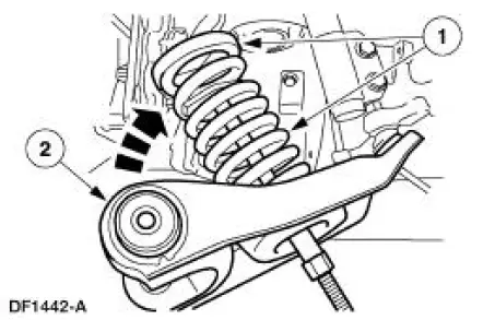
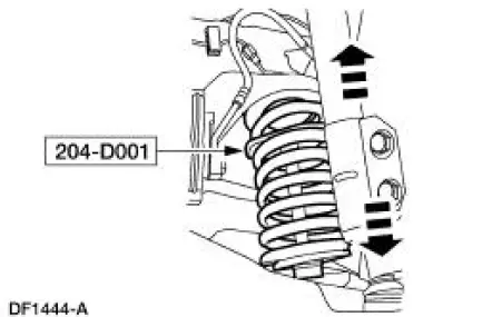
1. Install the spring.
1. Position the spring and spring insulator in the front suspension lower control arm.
2. Swing the arm into the fender well.
2. Position a jack stand under the front suspension lower control arm inboard of the spring seat and raise the arm into position.
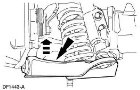
3. NOTE: The front suspension lower arm nuts must be tightened with the suspension at curb height.
Install the bolts and nuts. Do not tighten the bolts at this time.
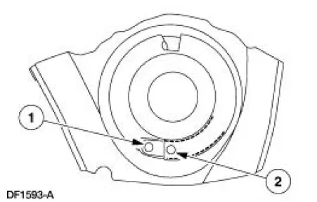
4. Make sure the spring is correctly positioned in the front suspension lower arm.
1. Spring must not cover this hole.
2. Spring must cover this hole.
5. Remove the special tool.
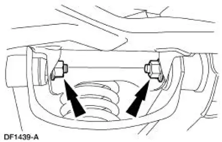
6. Move the jack stand under the front suspension lower arm ball joint and raise the suspension until the shock absorber is compressed to the previously established alignment mark (curb height).
7. Tighten the nuts.
8. Remove the jack stand.
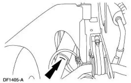
9. Install the power rack and pinion steering gear.
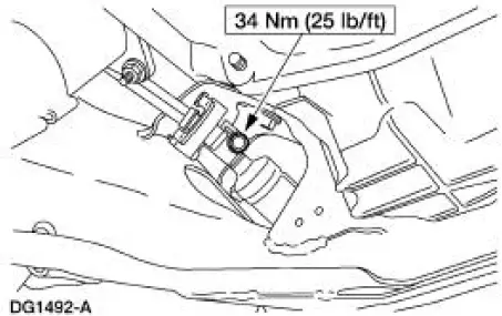
10. Position the intermediate shaft and install the bolt.
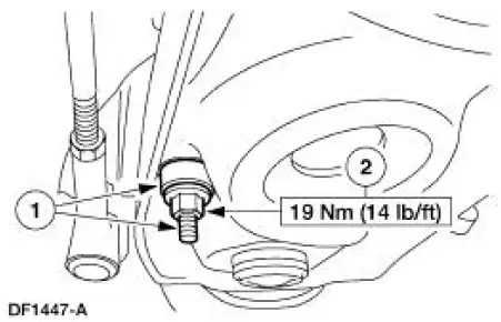
11. Connect the stabilizer bar link to the front suspension lower arm.
1. Install the link and bushing.
2. Install the nut.
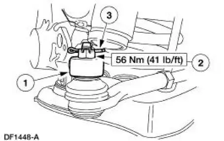
12. Connect the tie-rod end to the spindle.
1. Install the tie-rod end into the spindle.
2. Install the nut.
3. Install a new cotter pin.
13. Install the wheel and tire assembly. 14. Lower the vehicle.
15. Check wheel alignment. Adjust if necessary.
 Removal
CAUTION: Suspension fasteners are critical parts because they affect
performance of vital
components and systems and their failure can result in major service expense. A
new part with
the same part ...
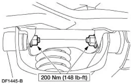
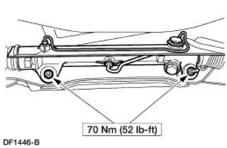
 Rear Suspension
Torque Specifications
WARNING: All vehicles are equipped with gas pressurized shock absorbers
which will
extend unassisted. Do not apply heat or flame to the shock absorbers during
removal or
comp ...
Other materials:
Parking Brake Control
Removal
1. CAUTION: If any component in the parking brake system requires
repair or if the
rear axle housing (4010) is removed, the cable tension must be released.
Place the parking brake control (2780) in the released position.
2. Remove the console.
3. ...
Piston - Pin Connecting Rod, Floating Pin
Material
Item
Specification
SAE 5W-20 Premium Synthetic
Blend Engine Oil
XO-5W20-QSP
WSS-M2C153-
H
Disassembly
1. Remove the clips.
2. Remove the piston pin from the piston and connecting rod assembly.
3. Remove the connecting rod ...
Valve Spring Strength
Special Tool(s)
Pressure Gauge, Valve/Clutch
Spring
303-006 (TOOL-6513-DD) or
equivalent
1. Use a Valve/Clutch Spring Pressure Gauge to check the valve spring for
correct strength at the
specified valve spring length.
Refer to the appr ...
