Ford Mustang (1999-2004) Service Manual: Master Cylinder Priming - 4.6L
1. CAUTION: Use only bleed screws on the engine side of the brake master cylinder (2140). The hydro-boost bleed screw, located near the dash on the hydro-booster casting, is for the booster cavity filled with power steering fluid, not brake fluid.
Connect a clear waste line to the bleed screw closet to the booster first and the other end in a container partially filled with recommended brake fluid.
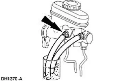
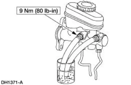
2. Open the bleeder screw, have an assistant push the brake pedal down slowly through full travel, close the bleeder screw, then return brake pedal slowly to full released position. Wait five seconds, then repeat operation until air bubbles cease to appear.
3. Repeat Step 2 for bleeder screw farthest from hydro-booster.
 Master Cylinder Priming - In-Vehicle or Bench
WARNING: Brake fluid contains polyglycol ethers and polyglycols. Avoid
contact with
eyes. Wash hands thoroughly after handling. If brake fluid contacts eyes, flush
eyes with
running water for 15 min ...
 Four Wheel Anti-Lock Brake System (4WABS) Hydraulic Control Unit (HCU)
NOTE: This procedure only needs to be performed if the 4-wheel
anti-lock brake (4WABS) hydraulic
control unit (HCU) has been installed new or if the HCU lines have been
opened.
1. Clean all ...
Other materials:
Radiator
Material
Item
Specification
Motorcraft Premium Gold
Engine Coolant
VC-7-A (in Oregon VC-7-B)
(yellow color)
WSS-M97B51-
A1
Removal and Installation
NOTE: Radiator removal and installation is similar for both 3.8L and
4.6L vehicles. ...
Sensor - Rear
Removal
1. Remove the rear passenger seat.
2. Disconnect the rear anti-lock brake sensor electrical connector.
3. Raise and support the vehicle.
4. Remove the rear anti-lock brake sensor harness from the floor pan.
5. Remove the anti-lock brake senso ...
Vacuum Hose Repair - Mini-Tube
Special Tool(s)
Vacuum Pump Kit
416-D002 (D95L-7559-A) or
equivalent
1. Measure the length of the damaged area of the mini-tube vacuum hose.
2. Cut a piece of standard 1/8 inch inner diameter vacuum hose approximately 25
mm (1 inch
longer t ...
