
Ford Mustang (1999-2004) Service Manual: Four Wheel Anti-Lock Brake System (4WABS) Hydraulic Control Unit (HCU)
NOTE: This procedure only needs to be performed if the 4-wheel anti-lock brake (4WABS) hydraulic control unit (HCU) has been installed new or if the HCU lines have been opened.
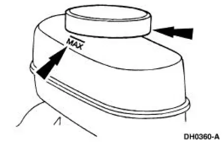
1. Clean all dirt from and remove the brake master cylinder filler cap (2162), and fill the brake master cylinder reservoir (2K478) with the specified brake fluid.
2. Connect a clear waste line to the RH rear bleeder screw (2208) and the other end in a container partially filled with recommended brake fluid.
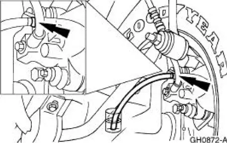
3. Loosen the RH rear bleeder screw until a stream of brake fluid comes out. While the assistant maintains pressure on the brake pedal (2455), tighten the RH rear bleeder screw.
- Repeat until clear, bubble-free fluid comes out.
- Refill the brake master cylinder reservoir as necessary.
4. Tighten the RH rear bleeder screw, and disconnect the waste line.
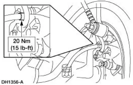
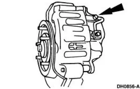
5. Repeat Steps 2, 3 and 4 for the LH rear bleeder screw, the RH front disc brake caliper (2B120) bleeder screw, and the LH front disc brake caliper bleeder screw, in that order.
6. Connect the scan tool DCL cable adapter into the vehicle data link connector (DLC) under the dash, and follow the scan tool instructions.
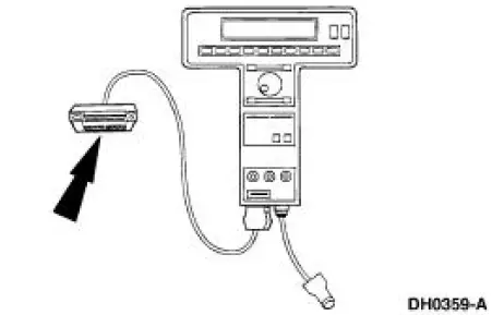
7. Repeat the system bleed procedure as outlined in Steps 1 through 5.
 Master Cylinder Priming - 4.6L
1. CAUTION: Use only bleed screws on the engine side of the
brake master cylinder
(2140). The hydro-boost bleed screw, located near the dash on the
hydro-booster
casting, is for the booster ...
 Caliper
1. NOTE: It is not necessary to do a complete brake system
bleed if only the disc brake caliper
(2B120) was disconnected.
Place a box end wrench on the disc brake caliper bleeder screw (2208). ...
Other materials:
Latch - Door
Removal
1. Remove the door trim panel (23942). For additional information,
refer to Section.
2. Release the actuating rods by opening the clips.
3. Using a screwdriver, release the lock cylinder actuating rod.
4. Remove the door latch screws.
5. ...
Planetary Gear Support Assembly and Planetary One-Way
Clutch
Disassembly and Assembly
1. NOTE: Inspect the outer and inner races for scores or damaged
surface areas where rollers
contact the races. Inspect the rollers and springs for excessive wear or damage.
Inspect the
spring and cage for bent or damaged ...
Catalyst Monitor Sensor
Special Tool(s)
Socket, Exhaust Gas Oxygen
Sensor
303-476 (T94P-9472-A)
Material
Item
Specification
Penetrating and Lock Lubricant
or equivalent
E8AZ-19A501-
B
Removal and Installation
1. Disconnect the battery ground ...
